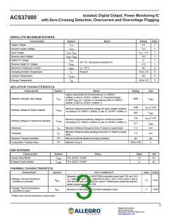
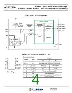
Isolated, Digital Output, Power Monitoring IC
with Zero-Crossing Detection, Overcurrent and Overvoltage Flagging
ACS37800
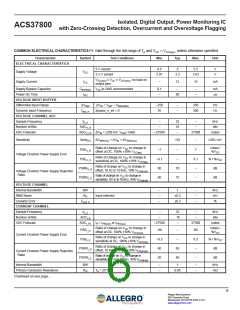
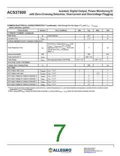
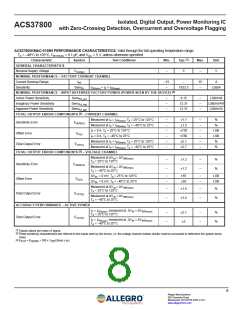
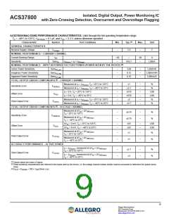
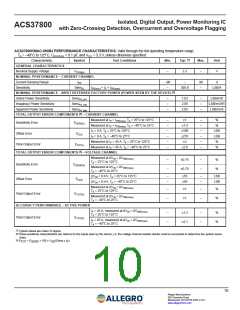
COMMON ELECTRICAL CHARACTERISTICS [1] (continued): Valid through the full range of TA and VCC = VCC(typ)
,
unless otherwise specified
Characteristic
Symbol
Test Conditions
Min.
Typ.
Max.
Unit
CURRENT CHANNEL (continued)
RMS Noise
NI
Input referred
–
–
±0.1
±1.5
–
–
A
Linearity Error
ELIN_I
%
OVERCURRENT FAULT CHARACTERISTICS
Time from IP rising above IFAULT until
VFAULT < VFAULT(max) for a current
step from 0 to 1.2 × IFAULT; 10 kΩ and
100 pF from DIO_1 to ground;
fltdly = 0
Fault Response Time
tRF
–
5
–
μs
Internal Bandwidth
BW
–
–
200
0.06 × FS
–
–
–
kHz
A
Fault Hysteresis [2]
IHYST
IFAULT
Fault Range
Set using fault field in EEPROM
0.65 × FS
2.00 × FS
A
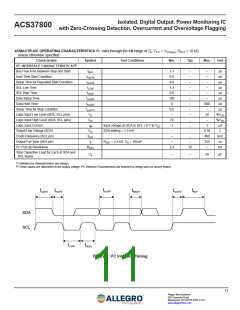
VOLTAGE ZERO CROSSING
Voltage Zero-Crossing Delay
DIO PINS
td
–
250
–
µs
DIO Output High Level
VOH(DIO) VCC = 3.3 V
VOL(DIO) VCC = 3.3 V
3
–
–
–
–
–
–
–
–
0.3
–
V
V
V
V
V
V
DIO Output Low Level
DIO Input Voltage for Address Selection 0
DIO Input Voltage for Address Selection 1
DIO Input Voltage for Address Selection 2
DIO Input Voltage for Address Selection 3
VADD0
VADD1
VADD2
VADD3
VCC = 3.3 V
VCC = 3.3 V
VCC = 3.3 V
VCC = 3.3 V
0
1.1
2.2
3.3
–
–
–
[1] Device may be operated at higher primary current levels (IP), ambient temperatures (TA), and internal leadframe temperatures, provided that the maximum junction
temperature (TJ(max)) is not exceeded.
[2] After IP goes above IFAULT, tripping the internal fault comparator, IP must go below IFAULT – IHYST before the internal fault comparator will reset.
7
Allegro MicroSystems
955 Perimeter Road
Manchester, NH 03103-3353 U.S.A.
www.allegromicro.com

 ALLEGRO [ ALLEGRO MICROSYSTEMS ]