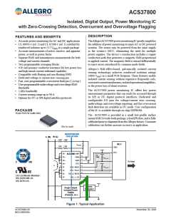
Isolated, Digital Output, Power Monitoring IC
with Zero-Crossing Detection, Overcurrent and Overvoltage Flagging
ACS37800
Table of Contents
Device EEPROM Settings................................................ 19
Voltage Measurement...................................................... 19
Current Measurement...................................................... 20
Configuring the Device for DC Applications ........................... 21
Device EEPROM Settings................................................ 21
Voltage Measurement...................................................... 21
Current Measurement...................................................... 21
RMS and Power Accuracy vs. Operation Point....................... 21
RMS and Power Output Error vs. Applied Input................... 21
15B5 IRMS and Power Error ........................................... 22
30B3 IRMS and Power Error ........................................... 22
90B3 IRMS and Power Error ........................................... 22
Digital Communication........................................................ 23
Communication Interfaces................................................ 23
SPI................................................................................ 23
Registers and EEPROM .................................................. 23
EEPROM Error Checking and Correction (ECC)................. 25
I2C Slave Adressing ........................................................ 25
EEPROM/Shadow Memory Map.......................................... 26
Register Details – EEPROM............................................. 27
Volatile Memory Map....................................................... 32
Register Details – Volatile ................................................ 33
Application Information ....................................................... 38
Thermal Rise vs. Primary Current ..................................... 38
ASEK37800 Evaluation Board Layout................................ 38
Recommended PCB Layout ................................................ 39
Package Outline Drawing.................................................... 40
Features and Benefits........................................................... 1
Description.......................................................................... 1
Package ............................................................................. 1
Typical Application................................................................ 1
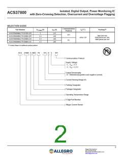
Selection Guide ................................................................... 2
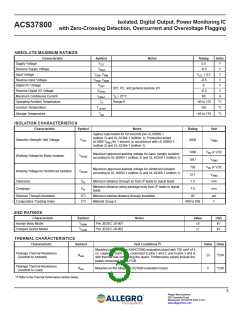
Absolute Maximum Ratings................................................... 3
Isolation Characteristics........................................................ 3
ESD Ratings........................................................................ 3
Thermal Characteristics ........................................................ 3
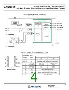
Functional Block Diagram ..................................................... 4
Pinout Diagram and Terminal List........................................... 4
Electrical Characteristics....................................................... 6
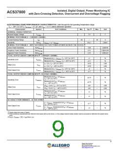
15B5 Performance Characteristics ......................................... 8
30B3 Performance Characteristics ......................................... 9
90B3 Performance Characteristics ....................................... 10
I2C Operating Characteristics ...............................................11
SPI Operating Characteristics.............................................. 12
Theory of Operation ........................................................... 13
Introduction.................................................................... 13
Voltage and Current Measurements .................................. 13
Overcurrent Measurement Path........................................ 13
Trim Methods ................................................................. 13
Power Calculations ......................................................... 14
Operational Block Diagram.................................................. 15
Configurable Settings ...................................................... 16
Configuring the DIO Pins (I2C Devices) ............................ 16
Configuring the Device for AC Applications............................ 19
5
Allegro MicroSystems
955 Perimeter Road
Manchester, NH 03103-3353 U.S.A.
www.allegromicro.com

 ALLEGRO [ ALLEGRO MICROSYSTEMS ]