Photoelectric Smoke Detector
with Interconnect and Timer
A5358
Selection Guide
Part Number
A5358CA
A5358CA-T
A5358CLWTR-T
Pb-free
–
Yes
Package
Packing
25 pieces / tube
25 pieces / tube
1000 pieces / reel
16-pin DIP through hole
16-pin DIP through hole
16-pin SOICW surface mount
Yes
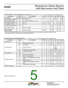
Absolute Maximum Ratings*
Characteristic
Symbol
VDD
Notes
Referenced to VSS
Rating
–0.5 to 15
–0.3 to VDD+0.3
10
Units
V
Supply Voltage Range
Input Voltage Range
Input Current
VIN
Referenced to VSS
V
IIN
mA
ºC
Operating Ambient Temperature Range
Maximum Junction Temperature
Storage Temperature Range
TA
–25 to 75
150
TJ(max)
ºC
T
stg
–55 to 125
ºC
*CAUTION: BiCMOS devices have input static protection but are susceptible to damage if exposed to extremely high static electrical
charges.
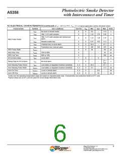
Thermal Characteristics
Characteristic
Symbol
Test Conditions*
Value Units
Package A, on 4-layer PCB based on JEDEC standard
38
48
ºC/W
ºC/W
Package Thermal Resistance
RθJA
Package LW, on 4-layer PCB based on JEDEC standard
*Additional thermal information available on Allegro website.
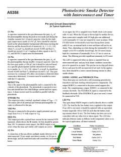
Terminal List Table
Number
Name
Function
Sets photoamplifier gain in supervisory mode
Sets photoamplifier gain in standby mode
Photoamplifier input
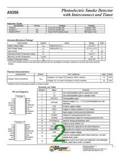
Pin-out Diagrams
1
C1
2
3
C2
Package A
DETECT
16 TEST
C1
C2
1
2
3
4
5
6
7
8
15 HUSH
Strobed supply (VDD – 5 V) for photoamplifier low-side
reference
4
STROBE
14 VSS
DETECT
STROBE
VDD
13 TIMING RES
12 OSC CAP
11 LED
5
6
VDD
IRED
Positive supply voltage
IRED
Output to smoke chamber IR LED driver
Input-output to interconnected detectors
Output for driving piezoelectric horn
Complementary output for driving piezoelectric horn
Input for driving piezoelectric horn
Output to drive visible LED
10 FEEDBACK
I/O
7
I/O
9
HORN2
HORN1
8
HORN1
HORN2
FEEDBACK
LED
9
10
11
12
13
14
Package LW
16 TEST
C1
C2
1
2
3
4
5
6
7
8
OSC CAP
TIMING RES
VSS
Connection for capacitor to set clock frequency
Connection for resistor to set clock frequency
Negative supply voltage
15 HUSH
14 VSS
DETECT
STROBE
VDD
13 TIMING RES
12 OSC CAP
11 LED
Input for photoamplifier timer mode reference; can also
disable timer mode
IRED
15
16
HUSH
TEST
10 FEEDBACK
I/O
9
HORN2
HORN1
Enables push-to-test mode and diagnostic test/calibration
mode; starts timer mode, if enabled
Allegro MicroSystems, LLC
115 Northeast Cutoff
2
Worcester, Massachusetts 01615-0036 U.S.A.
1.508.853.5000; www.allegromicro.com

 ALLEGRO [ ALLEGRO MICROSYSTEMS ]