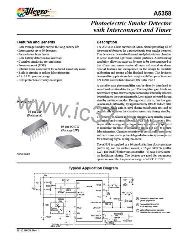
Photoelectric Smoke Detector
with Interconnect and Timer
A5358
OSC CAP (Oscillator Capacitor) Pin
the horn drivers and the I/O pin, and the LED blinks once every
0.67 s. If the test fails, the LED will not blink, the horn will not
sound, and the I/O pin will remain low. When the pushbutton is
released, the input returns to VSS due to the internal pull down.
After one oscillator cycle, the amplifier gain returns to normal,
and after three additional IRED pulses (less than one second), the
device exits this mode and returns to standby. This high-to-low
transition on TEST also resets and starts the 10-minute (nominal)
“hush” timer mode, if the mode is enabled via the HUSH pin.
A capacitor between this pin and VDD, along with a parallel
resistor, forms part of a two-terminal oscillator and sets the inter-
nal clock low time. With component values shown, this nominal
time is 10.4 ms and essentially the oscillator period. The internal
clock low time can be calculated by:
Tlow = 0.693 × ROSCCAP × COSCCAP
TIMING RES (Timing Resistor) Pin
.
A resistor between this pin and OSC CAP is part of the two-
terminal oscillator and sets the internal clock high time, which is
also the IRED pulse width. With component values shown, this
time is nominally 105 ꢀs. The internal clock high time can be
calculated by:
Diagnostic Test/Calibration Mode is available to facilitate
calibration and test of the IC and the assembled detector. It is
initiated by pulling TEST below VSS by continuously drawing
400 ꢀA from the pin for at least one clock cycle on OSC CAP.
The current should not exceed 800 ꢀA and under these condi-
tions, TEST pin voltage will clamp at approximately 250 mV
below VSS. One option is to connect TEST to a –5 V supply
through a 12 kΩ resistor. In this mode, certain device pins are
reconfigured as described in table 1. The IRED pulse rate is
Thigh = 0.693 × RTIMINGRES × COSCCAP
.
VSS Pin
This pin is connected to the negative supply potential (usually
ground).
HUSH Pin
Table 1. Alternate Pin Configuration During Diagnostic
Test/Calibration Mode
This input pin has an internal pull-down device and serves two
purposes in standby mode. It serves to enable/disable entering
the internal 10-minute (nominal) “hush” timer mode, and also
as the reference for the smoke comparator during timer mode.
When the voltage on this pin is greater than 1.5 V, entering timer
mode is enabled, and a high-to-low transition on TEST resets
and starts timer mode. If use of timer mode is not desired, this
pin can be connected to VSS or left open, and a voltage of less
than 0.5 V on the pin will disable timer mode. During timer
mode, the smoke comparator reference is established by a resis-
tive divider (Rx1 and Rx2) between the VDD and STROBE
pins and allows the detector to operate with reduced sensitivity
during timer mode. This allows the user to hush alarms caused
by nuisance smoke or steam (such as from cooking). When not
in timer mode, the smoke comparator reference is set internally
to approximately VDD – 3.5 V.
Pin Name
Alternate Configuration
Disabled as an output. A logic high on this pin places the
photoamplifier output on pin C1 or C2 as determined by
the HUSH pin. The amplifier output appears as pulses.
I/O
If the I/O pin is high, this pin controls the amplifier gain
capacitor. If this pin is low, normal gain is selected
and the amplifier output is on pin 1. If this pin is high,
supervisory gain is selected and the amplifier output is
on pin C2.
HUSH
NOTE: If I/O is low, four rising edges on this pin will
cause the device to exit diagnostic/calibration mode and
enter an Allegro-defined test mode.
If the I/O pin is high and the HUSH pin is low (normal
gain), taking this pin to a high logic level increases the
amplifier gain by ≈10% (hysteresis).
FEED-
BACK
TEST Pin
This pin has an internal pull-down device and is used to manu-
ally invoke two test modes and timer mode.
This pin may be driven by an external clock source.
OSC CAP Driving this pin low and high drives the internal clock low
and high. The external RC network may remain intact.
Push-to-Test mode is initiated by a voltage greater than approxi-
mately VDD – 0.5 V on this pin (usually the depression of a
normally-open pushbutton switch to VDD). After one oscilla-
tor cycle, the amplifier gain is increased by internal selection
of C1 so that background reflections in the smoke chamber can
be used to simulate a smoke condition, and IRED pulses every
336 ms (nominal). After the third IRED pulse (three consecu-
tive simulated smoke conditions), the successful test activates
This pin is reconfigured as the smoke integrator output.
Three consecutive smoke detections will cause this pin
HORN1
to go high and three consecutive no-smoke detections
cause this pin to go low.
This pin becomes a low-battery indicator. The open-drain
LED
NMOS output is normally off. If VDD falls below the low-
battery threshold, the output turns on.
Allegro MicroSystems, LLC
115 Northeast Cutoff
8
Worcester, Massachusetts 01615-0036 U.S.A.
1.508.853.5000; www.allegromicro.com

 ALLEGRO [ ALLEGRO MICROSYSTEMS ]