Photoelectric Smoke Detector
with Interconnect and Timer
A5358
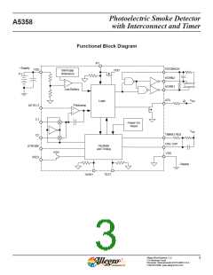
Pin and Circuit Description
(In Typical Application)
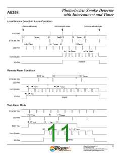
As an input, the I/O is sampled every fourth clock cycle (nomi-
nally 42 ms). When the I/O pin is driven high by another device,
three consecutive samples with I/O high plus one additional
cycle (nominally 10.5 ms) are required to cause an alarm. If the
I/O falls below its threshold at any time during those (nomi-
nally) 95 ms, an internal latch is reset and there will not be an
alarm. Thus, depending on when during the (nominally) 42 ms
sample cycle I/O is initially forced high, the I/O must remain
high for a minimum of (nominally) 95 to 137 ms to cause an
alarm. This filtering provides significant immunity to I/O noise.
C1 Pin
A capacitor connected to this pin determines the gain, Ae, of
the photoamplifier during the push-to-test mode and during the
chamber monitor test. A typical capacitor value for this high-
gain (supervisory) mode is 0.047 ꢀF, but it should be selected
based on the photochamber background reflections reaching the
detector and the desired level of sensitivity. Ae = 1+(C1/10),
where C1 is in pF. Ae should not exceed 10,000 and thus C1
should not exceed 0.1 ꢀF. Coupling of other signals to the C1,
C2, and DETECT inputs must be minimized.
C2 Pin
A capacitor connected to this pin determines the gain, Ae, of
the photoamplifier during standby. A typical capacitor value for
this low-gain mode is 4700 pF, but it should be selected based
on a specific photochamber and the desired level of sensitiv-
ity to smoke. Ae = 1+(C2/10), where C2 is in pF. Ae should not
exceed 10,000 and thus C2 should not exceed 0.1 ꢀF. This gain
increases by a nominal 10% after a local alarm is detected (three
consecutive detections). A resistor must be installed in series
with the C2 capacitor.
The LED is suppressed when an alarm is signaled from an
interconnected unit, and any local alarm condition causes this
pin to be ignored as an input. This pin has an on-chip pull-down
device and must be left unconnected if not used. In the applica-
tion, there should be a series current-limiting resistor to other
smoke alarms.
HORN1, HORN2, and FEEDBACK Pins
These three pins are used with a self-resonating piezoelectric
transducer and horn-starting external passive components. The
output HORN1 is connected to the piezo metal support elec-
trode. The complementary output, HORN2, is connected to the
ceramic electrode. The FEEDBACK input is connected to the
feedback electrode. If the FEEDBACK pin is not used, it must
be connected to VSS.
DETECT Pin
This is the input to the photoamplifier and is connected to the
cathode of the photodiode. The photodiode is operated at zero
bias and should have low dark leakage current and low capaci-
tance. A shunt resistor must be installed in parallel with the
photodiode.
STROBE Pin
LED Pin
This output provides a strobed, regulated voltage of VDD – 5 V.
The minus side of all internal and external photoamplifier cir-
cuitry is referenced to this pin.
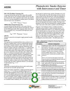
This open-drain NMOS output is used to directly drive a visible
LED. The load for the low-battery test is applied to this output.
If an LED is not used, it should be replaced with an equivalent
resistor (typically 500 to 1000 Ω) such that the battery load-
ing remains about 10 mA. The low-battery test does not occur
coincident with any other test or alarm signal. The LED also
indicates detector status as follows (with component values as in
the typical application, all times nominal):
VDD Pin
This pin is connected to the positive supply potential and can
range from 6 to 12 V with respect to VSS.
IRED Pin
This output provides a pulsed base current for the external NPN
transistor, which drives the IR emitter. Its beta should be greater
than 100. To minimize noise impact, the IRED output is not
active when the horn and visible LED outputs are active.
Condition
Standby
Pulse Occurrence
Every 43 s
I/O Pin
Local Smoke
Remote Alarm
Test Mode
Every 0.67 s
No pulses
A connection at this pin allows multiple smoke detectors to be
interconnected. If any single unit detects smoke, its I/O pin is
driven high, and all connected units will sound their associated
horns.
Every 0.67 s
Every 10 s
Timer Mode
Allegro MicroSystems, LLC
115 Northeast Cutoff
7
Worcester, Massachusetts 01615-0036 U.S.A.
1.508.853.5000; www.allegromicro.com

 ALLEGRO [ ALLEGRO MICROSYSTEMS ]