A3982
DMOS Stepper Motor Driver with Translator
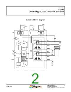
Functional Description
Device Operation. The A3982 is a complete stepper
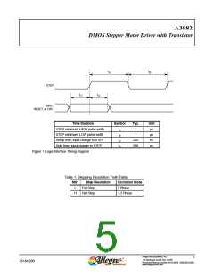
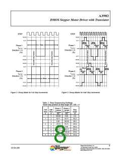
increment is determined by input MS1, as shown in table 1.
motor driver with a built-in translator for easy operation
with minimal control lines. It is designed to operate bipolar
stepper motors in full- and half-step modes. The currents in
each of the two output full-bridges and all of the N-channel
DMOS FETs are regulated with fixed off-time PMW (pulse
width modulated) control circuitry. At each step, the current
for each full-bridge is set by the value of its external current-
sense resistor (RS1 or RS2), a reference voltage (VREF), and
the output voltage of its DAC (which in turn is controlled by
the output of the translator).
Direction Input (DIR). This determines the direction of
rotation of the motor. When low, the direction will be clock-
wise and when high, counterclockwise. Changes to this input
do not take effect until the next STEP rising edge.
Internal PWM Current Control. Each full-bridge is
controlled by a fixed off-time PWM current control circuit
that limits the load current to a desired value, ITRIP. Ini-
tially, a diagonal pair of source and sink DMOS outputs are
enabled and current flows through the motor winding and
the current sense resistor, RSx. When the voltage across RSx
equals the DAC output voltage, the current sense compara-
tor resets the PWM latch. The latch then turns off either the
source DMOS FET (when in Slow Decay Mode) or the sink
and source DMOS FETs (when in Mixed Decay Mode).
At power-on or reset, the translator sets the DACs and the
phase current polarity to the initial Home state (shown in
figures 2 and 3), and the current regulator to Mixed Decay
Mode for both phases. When a step command signal occurs
on the STEP input, the translator automatically sequences
the DACs to the next level and current polarity. (See table 2
for the current-level sequence.) The step resolution is set by
input MS1, as shown in table 1.
The maximum value of current limiting is set by the selec-
tion of RSx and the voltage at the VREF pin. The transcon-
ductance function is approximated by the maximum value of
current limiting, ITripMAX (A), which is set by
When stepping, if the new output levels of the DACs are
lower than their previous output levels, then the decay mode
for the active full-bridge is set to Mixed. If the new output
levels of the DACs are higher than or equal to their previous
levels, then the decay mode for the active full-bridge is set to
Slow. This automatic current decay selection improves step-
ping performance by reducing the distortion of the current
waveform that results from the back EMF of the motor.
ITripMAX = VREF /(8 R )
×
S
where RS is the resistance of the sense resistor (Ω) and VREF
is the input voltage on the REF pin (V).
The DAC output reduces the VREF output to the current
sense comparator in precise steps, such that
Itrip = (%ITripMAX /100)
I
TripMAX
RESET Input (RESET). The RESET input sets the
translator to a predefined Home state (shown in figures 2
and 3), and turns off all of the DMOS outputs. All STEP
inputs are ignored until the RESET input is set to high.
×
(See table 2 for %ITripMAX at each step.)
It is critical that the maximum rating (0.5 V) on the SENSE1
and SENSE2 pins is not exceeded.
Step Input (STEP). A low-to-high transition on the STEP
input sequences the translator and advances the motor one
increment. The translator controls the input to the DACs and
Fixed Off-Time. The internal PWM current control cir-
cuitry uses a one-shot circuit to control the duration of time
the direction of current flow in each winding. The size of the that the DMOS FETs remain off. The one shot off-time, tOFF
,
Allegro MicroSystems, Inc.
6
115 Northeast Cutoff, Box 15036
26184.28B
Worcester, Massachusetts 01615-0036 (508) 853-5000
www.allegromicro.com

 ALLEGRO [ ALLEGRO MICROSYSTEMS ]