A4931
3-Phase Brushless DC Motor Pre-Driver
Functional Description
blanking function. The duration is fixed at 1.5 μs.
Current Regulation Load current is regulated by an internal
fixed off-time PWM control circuit. When the outputs of the full
bridge are turned on, current increases in the motor winding until
it reaches a value, ITRIP, given by:
Synchronous Rectification When a PWM-off cycle is
triggered, either by a chop command on ENB or by an internal
fixed off-time cycle, load current recirculates. The A4931 syn-
chronous rectification feature turns on the appropriate MOSFETs
during the current decay, and effectively shorts out the body
diodes with the low RDS(on) driver. This lowers power dissipation
significantly and can eliminate the need for external Schottky
diodes.
ITRIP = 200 mV / RSENSE .
When ITRIP is reached, the sense comparator resets the source
enable latch, turning off the source driver. At this point, load
inductance causes the current to recirculate for the fixed off-time
period.
Brake Mode A logic low on the BRAKEZ pin activates Brake
mode. A logic high allows normal operation. Braking turns on all
three sink drivers, effectively shorting out the motor-generated
BEMF. The BRAKEZ input overrides the ENB input and also the
Lock Detect function.
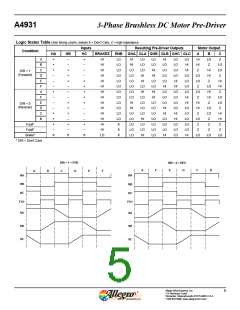
Enable Logic The Enable input terminal (ENB pin) allows
external PWM. ENB low turns on the selected sink-source pair.
ENB high switches off the appropriate drivers and the load
current decays. If ENB is held low, the current will rise until it
reaches the level set by the internal current control circuit. Typi-
cally PWM frequency is in 20 kHz to 30 kHz range. If the ENB
high pulse width exceeds 3 ms, the gate outputs are disabled. The
Enable logic is summarized in the following table:
It is important to note that the internal PWM current control cir-
cuit does not limit the current when braking, because the current
does not flow through the sense resistor. The maximum current
can be approximated by VBEMF / RLOAD. Care should be taken to
insure that the maximum ratings of the A4391 are not exceeded
in the worse case braking situation, high speed and high inertial
load.
ENB Pin Setting
0
Outputs
On
Outputs State
Drive
Slow Decay with
Synchronous
Rectification
1
Source Chopped
Off
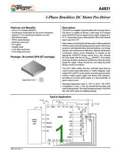
HBIAS Function This function provides a power supply of
7.5 V, current-limited to 30 mA. This reference voltage is used to
power the logic sections of the IC and also to power the external
Hall elements.
1 for > 3 ms typical
Disable
Fixed Off-Time The A4931 fixed off-time is set to 24 μs
nominal.
PWM Blank Timer When a source driver turns on, a current
spike occurs due to the reverse recovery currents of the clamp
diodes as well as switching transients related to distributed
capacitance in the load. To prevent this current spike from errone-
ously resetting the source Enable latch, the sense comparator is
blanked. The blanking timer runs after the off-time counter com-
pletes, in order to provide the blanking function. The blanking
timer is reset when ENB is chopped or DIR is changed. With
external PWM control, a DIR change or an ENB on triggers the
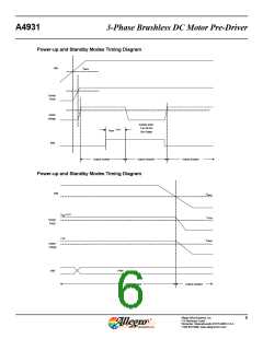
Standby Mode To prevent excessive power dissipation due
to the current draw of the external Hall elements, Standby mode
turns off the HBIAS output voltage. Standby mode is triggered
by holding ENB high for longer than 3 ms. Note that Brake mode
overrides Standby mode, so hold the BRAKEZ pin high in order
to enter Standby mode.
Charge Pump The internal charge pump is used to generate a
supply above VBB to drive the high-side MOSFETs. The volt-
Allegro MicroSystems, Inc.
115 Northeast Cutoff
7
Worcester, Massachusetts 01615-0036 U.S.A.
1.508.853.5000; www.allegromicro.com

 ALLEGRO [ ALLEGRO MICROSYSTEMS ]