[ASAHI KASEI]
[AK7740ET]
Functional Description
(1) Various setting
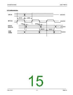
1-1) SMODE : slave and master mode selector pin
Sets LRCLK and BITCLK to either input or output.
a) Slave mode :SMODE="L"
b) Master mode: SMODE="H"
LRCLK (1fs) and BITCLK (64fs or 48fs ) are inputs.
LRCLK (1fs) and BITCLK (64fs) are outputs.
Note) SMODE is required to be fixed “L” or “H”. After releasing initial reset ( INIT_RESET =”L”→”H”), this
pin may only change during a system reset state ( S_RESET ="L") . In slave mode, phase matching between
internal and external clocks start when system reset is released (see (8.(4)), resetting). Do not change SMODE
during normal operation.
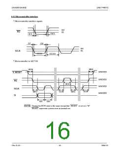
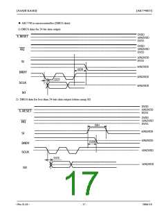
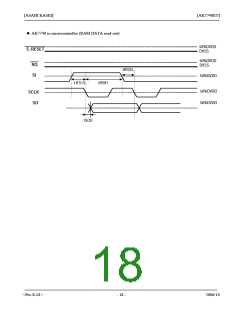
(2) Control registers
The control registers can be set via the microcontroller interface in addition to the control pins.These registers
consist of four parts, and each register contains 8-bits. For details about writing to the control registers, see the
description of the microcontroller interface.This section describes the control register maps.
TEST: for TEST (input 0,X: input data ignored, but a 0 should be written).
Command
Code
Name
D7
D6
D5
D4
D3
D2
D1
D0 Default
Write Read
60h
64h
68h
6Ch
70h
74h
78h
7Ch
CONT0
CONT1 DATARAM
CONT2
CONT3
CKS1
CKS0
RM
SW1
DIF
DIF1
DIF0
DISCK SELCKO
X
X
X
X
00h
00h
00h
00h
BANK[1] BANK[0] CMP_N
SW0
ISEL[0]
SS[1]
TEST
PSAD
SS[0]
TEST
TEST
SW2
ISEL[2]
PSDA2
SW3
PSDA1
OUTAE
ISEL[1]
Data can be loaded into the control registers only when S_RESET = "L". Do not attempt to change any value in
the control register when S_RESET = "H”.
1. CONT0 can be set only when system reset ( S_RESET = "L").
2. CONT1~3 should be set when system reset ( S_RESET = "L"), otherwise noise will be output.
Prior to changing the input selector (CONT3: ISEL[2:0], clocks should be applied and the ADC should be in
normal operation mode. The ADC is powered up by setting CONT3:PSAD = 0. Spontaneous changes to the
input selector may result in output noise (generated in the ADC data), so an external mute circuit after the DAC
output may be required.
3. Default setting is the same value that is initialized by initial reset ( INIT_RESET =”L” ).
<Pre-E-01>
- 19 -
2006/10

 AKM [ ASAHI KASEI MICROSYSTEMS ]