[AK4679]
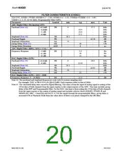
FILTER CHARACTERISTICS (CODEC)
(Ta=25°C; AVDD = PVDD =DVDD=1.7 ∼ 2.0V; SVDD=3.0 ∼ 5.5V, TVDDA=TVDDE =1.6 ∼ 3.6V,
VDDE=1.1~1.3V; fs=44.1kHz; Programmable Filter=OFF)
Parameter
Symbol
min
typ
max
Unit
ADC Digital Filter (Decimation LPF):
Passband (Note 44)
PB
0
-
-
-
-
19.4
19.9
22.1
-
-
-
20
0
17.3
-
-
-
kHz
kHz
kHz
kHz
kHz
dB
dB
1/fs
μs
±0.16dB
−0.66dB
−1.1dB
−6.9dB
Stopband (Note 44)
Passband Ripple
Stopband Attenuation
Group Delay (Note 45)
Group Delay Distortion
SB
PR
SA
GD
ΔGD
26.1
-
-
73
-
±0.16
-
-
-
-
ADC Digital Filter (HPF): HPFC1-0 bits = “00”
Frequency Response
FR
-
-
-
3.4
10
22
-
-
-
Hz
Hz
Hz
−3.0dB
−0.5dB
−0.1dB
DAC Digital Filter (LPF):
Passband (Note 44)
PB
0
-
20.0
-
-
±0.05
-
-
kHz
kHz
kHz
dB
dB
1/fs
±0.05dB
−6.0dB
-
24.1
-
54
-
22.05
-
-
-
25
Stopband (Note 44)
Passband Ripple
Stopband Attenuation
Group Delay (Note 45)
SB
PR
SA
GD
DAC Digital Filter (LPF) + SCF + SMF:
FR
-
-
dB
Frequency Response: 0 ∼ 20.0kHz
±1.0
Note 44. The passband and stopband frequencies scale with fs (system sampling rate).
For example, DAC is PB=0.454 x fs (@±0.05dB). Each response refers to that of 1kHz.
Note 45. The calculated delay time caused by digital filtering. This time is from the input of analog signal to setting of the
24-bit data of both channels from the input register to the output register of the ADC. This time includes group
delay of the HPF and Programmable filter. For the DAC, this time is from setting the 24-bit data of both channels
from the input register to the output of analog signal and includes selector block (SDMIN, PFMXL/R and
SRMXL/R), DRC, 5-band EQ and DATT-A. For the signal through the programmable filters, group delay is
increased 4/fs at Playback Mode from the value above if there is no phase changed by the IIR filter.
MS1402-E-06
2013/02
- 20 -

 AKM [ ASAHI KASEI MICROSYSTEMS ]