6
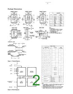
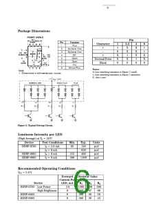
Package Dimensions
Pin
Character
1
1
0
X
X
0
2,3
X
X
1
X
4
X
X
X
1
0
8
1
1
X
X
0
+
–
1
Decimal Point
Blank
0
Notes:
0: Line switching transistor in Figure 7 cutoff.
1: Line switching transistor in Figure 7 saturated.
X: ‘don’t care.’
Figure 3. Typical Driving Circuit.
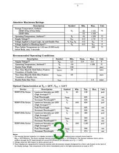
Luminous Intensity per LED
(Digit Average) at TA = 25°C
Device
HDSP-0783
Test Conditions
IF = 2.8 mA
IF = 8 mA
Min.
65
Typ.
140
620
Units
µcd
µcd
HDSP-0883
HDSP-0983
IF = 8 mA
IF = 8 mA
215
298
490
1100
µcd
µcd
Recommended Operating Conditions
VCC = 5.0 V
Forward
Resistor Value
Current Per
Device
HDSP-0783 Low Power
LED, mA
R1
R2
R3
300
68
56
43
2.8
8
8
1300 200
High Brightness
360
360
360
47
36
30
HDSP-0883
HDSP-0983
8

 AGILENT [ AGILENT TECHNOLOGIES, LTD. ]