4
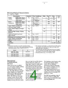
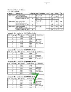
Electrical/Optical Characteristics
TA = –55°C to +100°C
Description
HDSP-078x Series
Symbol
ICC
Test Conditions
VCC = 5.5 V
Characters “5.” or
“B” displayed
Min. Typ.[7]
Max.
105
Unit
mA
Supply
Current
78
HDSP-079x/-088x/
-098x Series
120
175
Power
Dissipation
HDSP-078x Series
HDSP-079x/-088x/
-098x Series
PT
VCC = 5.5 V
Characters “5.” or
“B” displayed
390
690
573
963
mW
Logic, Enable and Blanking
Low-Level Input Voltage
Logic, Enable High-Level Input
Voltage
Blanking High-Voltage; Display
Blanked
Logic and Enable Low-Level
Input Current
V
VCC = 4.5 V
0.8
V
V
IL
V
IH
2.0
2.3
VBH
IIL
V
VCC = 5.5 V
–1.6
mA
Blanking Low-Level Input Current
Logic, Enable and Blanking
High-Level Input Current
IBL
IIH
V = 0.4 V
VCC = 5.5 V
V = 2.4 V
IH
–10
+40
µA
µA
IL
Weight
Leak Rate
1.0
gm
5 x 10⁻⁸ cc/sec
Notes:
4. The luminous intensity at a specific operating ambient
temperature, Iv(TA), may be approximated from the following
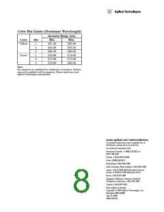
5. The dominant wavelength, λd, is derived from the CIE chroma-
ticity diagram and represents the single wavelength which
defines the color of the device.
exponential equation: Iv(TA) = Iv(25°C) e[k(T -25°C)]
.
A
6. The HDSP-088X and HDSP-098X series devices are categor-
ized as to dominant wavelength with the category designated
by a number on the back of the display package.
Device
K
HDSP-078 Series
HDSP-079x Series
–0.0131/°C
7. All typical values at VCC = 5.0 V and TA = 25°C.
HDSP-088x Series
HDSP-098x Series
–0.0112/°C
–0.0104/°C
Operational
line is at logic low and the data is
latched when the enable is at
logic high. Using the enable pulse
width and data setup and hold
times listed in the Recommended
Operating Conditions allows data
to be clocked into an array of
displays at a 6.7 MHz rate.
The blanking control input on the
hexadecimal displays blanks
(turns off) the displayed
information without disturbing
the contents of display memory.
The display is blanked at a
minimum threshold level of 2.0
volts. When blanked, the display
standby power is nominally 250
mW at TA = 25°C.
Considerations
Electrical
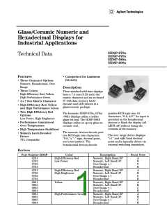
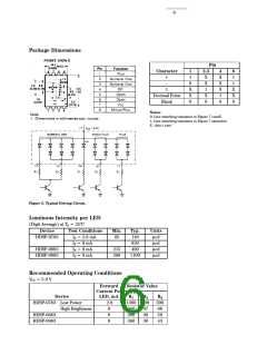
These devices use a modified
4 x 7 dot matrix of light emitting
diodes to display decimal/
hexadecimal numeric informa-
tion. The high efficiency red and
yellow displays use GaAsP/GaP
LEDs and the high performance
green displays use GaP/GaP
LEDs. The LEDs are driven by
constant current drivers, BCD
information is accepted by the
display memory when the enable
The decimal point input is active
low true and this data is latched
into the display memory in the
same fashion as the BCD data.
The decimal point LED is driven
by the on-board IC.
The ESD susceptibility of the IC
devices is Class A of MIL-STD-
883 or Class 2 of DOD-STD-1686
and DOD-HDBK-263.

 AGILENT [ AGILENT TECHNOLOGIES, LTD. ]