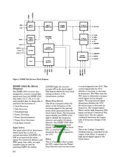
Clock Select
Input Sampler
Frame Mode. For more
information about this, refer to
Double Frame Mode.
The Clock Select accepts the high
speed digital signal from the VCO
and outputs an internal high
speed serial clock. The VCO
frequency is divided, based on the
DIV1/DIV0 inputs, to the input
signal’s frequency range. The
Clock Select output, accessible
through BCLK, is an internal
serial clock. It is phase and
frequency locked to the incoming
signal. This internal serial clock is
used by the Input Sampler to
sample the data. It is also used by
the Clock Generator to generate
the recovered frame rate clock.
The serial input signal is con-
verted into a serial bit stream,
using the extracted internal serial
clock from the Clock Select. This
output is sent to the frame
demux.
D-Field Decoder
The D-Field Decoder accepts the
data field of the incoming data
frame from the Frame Demux.
Based on information from the C-
Field Decoder, which determines
what type of data is being
received, the D-Field Decoder
restores the parallel data back to
its original form.
Frame Demux
The Frame Demux demultiplexes
the serial bit stream from the
Input Sampler into a 20 or 24 bit
wide parallel data word, based on
the setting of M20SEL. The most
significant 4 bits are sent to the
C-Field Decoder, while the
remaining 16 or 20 bits are sent
to the D-Field Decoder.
State Machine
The State Machine is used in full
duplex mode to perform the
functions of link startup, link
maintenance, and error checking.
By setting the SMRST0* and
SMRST1* low, the user, too, can
reset the state machine and
initiate link startup. SMRST1* is
usually connected to the transmit-
ters LOCKED output. STAT1 and
STAT0 denote the current state of
link during startup. ACTIVE is an
input normally driven by the
STAT1 and STAT0 outputs. This
ACTIVE input is retimed by
STRBOUT and presented to the
user as LINKRDY*. LINKRDY* is
an active low output that indicates
when the link is ready to transmit
data. Refer to The State Machine
Handshake Protocol section on
page 645 for more details.
By setting TCLKSEL high, the
user may input an external high
speed serial clock at TCLK. The
Clock Select accepts this signal
and directly outputs it as the
internal serial clock.
C-Field Decoder
The C-Field Decoder accepts the
control information from the
Frame Demux and determines
what kind of frame is being
received and whether or not it has
to be inverted. The control bits
are sent to the State Machine for
error checking. The decoded
information is sent to the D-Field
Decoder. CAV* is set low if the
incoming frame is control data.
DAV* is set low if the information
is data. If neither DAV* nor CAV*
is set low, then the incoming
frame is expected to be a fill
frame. If FLAGSEL is asserted,
the FLAG bit is restored to its
original form. Otherwise, FLAG is
used to differentiate between the
even and odd frames in Double
Clock Generator
The Clock Generator accepts the
serial clock generated from the
Clock Select and generates the
frame rate clock, based on the
setting of M20SEL. If M20SEL is
asserted, the incoming encoded
data frame is expected to be 24
bits wide (20 data bits and 4
control bits). The master
transition in the control section of
encoded data stream is expected
every 24 bits, and used to ensure
proper frame synchronization of
the output frame clock,
STRBOUT.
623

 AGILENT [ AGILENT TECHNOLOGIES, LTD. ]