balance and allow the receiver to
maintain frequency and phase
lock. The type of fill frames sent
(FF0 or FF1) is determined by the
FF input. In a duplex system, FF
is normally connected to the Rx’s
STAT1 pin.
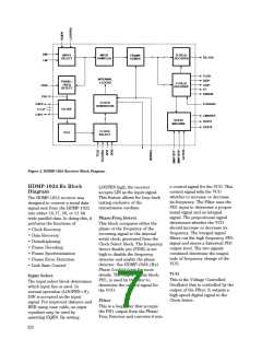
signals from the Control Logic,
the D-Field Encoder either
outputs the parallel information at
its data inputs (D0..D19) or the
designated Fill Frame. RST*,
when set low, resets the internal
chip registers.
Accumulator/Invert
The Accumulator/Invert block is
responsible for maintaining the
DC balance of the serial line. It
determines, based on history and
the sign of the current data frame,
whether or not the current frame
should be inverted to bring the
line closer to the desired 50%
duty cycle. INV is set high when
the data frame is inverted.
The C-Field Encoder, based on
the inputs at DAV*, CAV*,
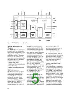
Frame Mux
The Frame Mux accepts the
output from the C-Field and D-
Field Encoders. The four control
bits are attached to the data bits,
either 16 or 20 data bits based on
the M20SEL input. This parallel
information, now either 20 or 24
bits wide, is multiplexed to a
serial line based on the internal
high speed serial clock.
FLAGSEL, and FLAG, supplies
four encoded bits to the frame
mux. This encoded data contains
the master transition (which the
receiver uses for frequency
locking), as well as information
regarding the data type: control,
data, or fill frame. In order for the
FLAG bit to be used as an
Output Select
In normal operation, the serial
data stream is placed at DOUT.
By asserting LOOPEN, the user
may also direct the serial data
stream to LOUT, which may be
used for loopback testing. When
LOOPEN is not asserted, LOUT is
disabled to reduce power
consumption.
additional data bit, FLAGSEL
must be set high for both the Tx
and the Rx.
SIGN
The sign circuitry determines the
cumulative sign of the outgoing
data frame, containing the data
and control bits. This is used by
the accumulator/inverter to
maintain DC balance for the
transmission line.
D-Field Encoder
The D-Field Encoder provides the
remaining parallel word data to
the frame mux. Based on control
621

 AGILENT [ AGILENT TECHNOLOGIES, LTD. ]