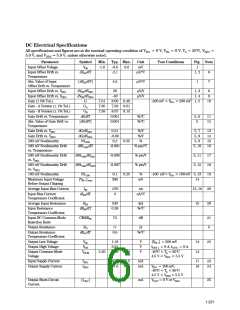
AC Electrical Specifications
All specifications and figures are at the nominal operating condition of VIN+ = 0 V, VIN- = 0 V, T = 25°C,
A
VDD1 = 5.0 V, and VDD2 = 5.0 V, unless otherwise noted.
Parameter
Symbol Min.
Typ. Max.
Unit
Test Conditions
IM = 1 kV
Fig.
Note
Rising Edge Isolation
Mode Rejection
IMRR
IMRF
IMRR
10
25
kV/µs
V
19, 20
26
Falling Edge Isolation
Mode Rejection
10
15
kV/µs
Isolation Mode Rejection
Ratio at 60 Hz
>140
dB
19
27
Propagation Delay to 10%
Propagation Delay to 50%
Propagation Delay to 90%
Rise/Fall Time (10%-90%)
Bandwidth (-3 dB)
tPD10
tPD50
tPD90
tR/F
2.0
3.4
6.3
4.3
85
3.3
5.6
9.9
6.6
µs
µs
-40°C < T < 85°C
21, 22
A
µs
µs
f-3dB
f-45°
VN
50
kHz
kHz
23, 24
Bandwidth (-45°)
35
RMS Input-Referred
Noise
300
µV rms Bandwidth = 100 kHz 25, 26
28
29
Power Supply Rejection
PSR
5
mV
p-p
Package Characteristics
All specifications and figures are at the nominal operating condition of VIN+ = 0 V, VIN- = 0 V, T = 25°C, VDD1
A
= 5.0 V, and VDD2 = 5.0 V, unless otherwise noted.
Parameter
Symbol Min. Typ. Max.
Unit
Test Conditions
Fig. Note
Input-Output Momentary
Withstand Voltage*
V
3750
V rms t = 1 min., RH ≤ 50%
30, 31
ISO
Input-Output Resistance
RI-O
1012 1013
Ω
TA = 25°C
TA = 100°C
f = 1 MHz
VI-O = 500 Vdc
30
1011
0.7
96
Input-Output Capacitance
CI-O
pF
30
32
Input IC Junction-to-
θjci
°C/W
Case Thermal Resistance
Output IC Junction-to-Case
Thermal Resistance
θjco
114
°C/W
*The Input-Output Momentary Withstand Voltage is a dielectric voltage rating that should not be interpreted as an input-output
continuous voltage rating. For the continuous voltage rating refer to the VDE 0884 Insulation Characteristics Table (if applicable), your
equipment level safety specification, or HP Application Note 1074, “Optocoupler Input-Output Endurance Voltage.”
1-222

 AGILENT [ AGILENT TECHNOLOGIES, LTD. ]