2
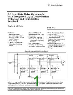
Typical Fault Protected
IGBT Gate Drive Circuit
The HCPL-316J is an easy-to-use,
intelligent gate driver which
configurable inputs, integrated
detection, under voltage
lockout (UVLO), “soft” IGBT
turn-off and isolated fault feed-
back provide maximum design
flexibility and circuit protection.
V
CE
makes IGBT V fault protection
CE
compact, affordable, and easy-to-
implement. Features such as user
HCPL-316J
1
2
3
4
5
6
7
8
V
V
V
V
16
15
IN+
E
C
BLANK
*
V
IN-
LED2+
D
DESAT
100 Ω
DESAT 14
CC1
+
–
+
–
µC
V
F
GND1
V
13
12
11
10
9
CC2
R
F
+
–
+
–
+
–
RESET
FAULT
V
C
R
G
*
V
V
CE
V
OUT
V
V
–
+
*
LED1+
EE
V
V
EE
LED1-
R
PULL-DOWN
CE
* THESE COMPONENTS ARE ONLY REQUIRED WHEN NEGATIVE GATE DRIVE IS IMPLEMENTED.
Figure 1. Typical Desaturation Protected Gate Drive Circuit, Non-Inverting.
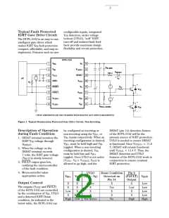
Description of Operation
during Fault Condition
1. DESAT terminal monitors the
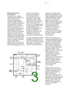
be configured as inverting or
DESAT (pin 14) detection feature
of the HCPL-316J will be the
primary source of IGBT protection.
UVLO is needed to ensure DESAT
non-inverting using the V
or
IN+
V
inputs respectively. When an
IN-
inverting configuration is desired,
must be held high and V
IGBT V voltage through
CE
V
is functional. Once V
> 11.6
IN+
IN-
UVLO+
D
DESAT
.
toggled. When a non-inverting
configuration is desired, V
V, DESAT will remain functional
until V < 12.4 V. Thus, the
2. When the voltage on the
DESAT terminal exceeds
IN-
IN+
UVLO-
must be held low and V
toggled. Once UVLO is not active
(V - V > V ), V is
DESAT detection and UVLO
features of the HCPL-316J work in
conjunction to ensure constant
IGBT protection.
7 volts, the IGBT gate voltage
(V
OUT
) is slowly lowered.
CC2
E
UVLO
OUT
3. FAULT output goes low,
notifying the microcontroller
of the fault condition.
allowed to go high, and the
4. Microcontroller takes
appropriate action.
UVLO
Desat Condition
Pin 6
(FAULT)
Output
V
IN+
V
IN-
(V
- V )
Detected on
Pin 14
V
OUT
CC2
E
Output Control
X
X
Low
X
X
X
X
Active
X
Yes
X
X
No
X
Low
X
X
High
Low
Low
Low
Low
High
The outputs (V
and FAULT)
OUT
X
X
X
of the HCPL-316J are controlled
by the combination of V , UVLO
and a detected IGBT Desat
condition. As indicated in the
below table, the HCPL-316J can
IN
High
High Low
Not Active

 AGILENT [ AGILENT TECHNOLOGIES, LTD. ]