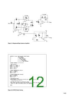
Theory of Operation
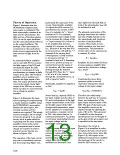
particularly the input part of the
circuit. Stated briefly, amplifier
A1 adjusts the LED current (IF),
and therefore the current in PD1
(IPD1), to maintain its “+” input
terminal at 0 V. For example,
since light from the LED falls on
both of the photodiodes, IPD2 will
be stabilized as well.
Figure 1 illustrates how the
HCNR200/201 high-linearity
optocoupler is configured. The
basic optocoupler consists of an
LED and two photodiodes. The
LED and one of the photodiodes
(PD1) is on the input leadframe
and the other photodiode (PD2) is
on the output leadframe. The
package of the optocoupler is
constructed so that each photo-
diode receives approximately the
same amount of light from the
LED.
The physical construction of the
package determines the relative
increasing the input voltage would amounts of light that fall on the
tend to increase the voltage of the
“+” input terminal of A1 above 0
V. A1 amplifies that increase,
causing IF to increase, as well as
IPD1. Because of the way that PD1
is connected, IPD1 will pull the “+”
terminal of the op-amp back
two photodiodes and, therefore,
the ratio of the photodiode
currents. This results in very
stable operation over time and
temperature. The photodiode
current ratio can be expressed as
a constant, K, where
toward ground. A1 will continue
to increase IF until its “+”
K = IPD2/IPD1
.
terminal is back at 0 V. Assuming
that A1 is a perfect op-amp, no
current flows into the inputs of
A1; therefore, all of the current
flowing through R1 will flow
through PD1. Since the “+” input
of A1 is at 0 V, the current
An external feedback amplifier
can be used with PD1 to monitor
the light output of the LED and
automatically adjust the LED
current to compensate for any
non-linearities or changes in light
output of the LED. The feedback
amplifier acts to stabilize and
linearize the light output of the
LED. The output photodiode then
converts the stable, linear light
output of the LED into a current,
which can then be converted back
into a voltage by another
Amplifier A2 and resistor R2 form
a trans-resistance amplifier that
converts IPD2 back into a voltage,
VOUT, where
VOUT = IPD2*R2.
through R1, and therefore IPD1 as
well, is equal to V /R1.
Combining the above three
equations yields an overall
expression relating the output
voltage to the input voltage,
IN
Essentially, amplifier A1 adjusts IF
so that
IPD1 = V /R1.
VOUT/V = K*(R2/R1).
IN
IN
amplifier.
Notice that IPD1 depends ONLY on
the input voltage and the value of
R1 and is independent of the light
output characteristics of the LED.
As the light output of the LED
changes with temperature, ampli-
fier A1 adjusts IF to compensate
and maintain a constant current
in PD1. Also notice that IPD1 is
Therefore the relationship
between V and VOUT is constant,
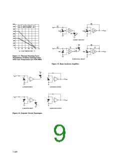
Figure 12a illustrates the basic
circuit topology for implementing
a simple isolation amplifier using
the HCNR200/201 optocoupler.
Besides the optocoupler, two
external op-amps and two
resistors are required. This simple
circuit is actually a bit too simple
to function properly in an actual
circuit, but it is quite useful for
explaining how the basic isolation
amplifier circuit works (a few
more components and a circuit
change are required to make a
practical circuit, like the one
shown in Figure 12b).
IN
linear, and independent of the
light output characteristics of the
LED. The gain of the basic isola-
tion amplifier circuit can be
adjusted simply by adjusting the
ratio of R2 to R1. The parameter
K (called K3 in the electrical
specifications) can be thought of
as the gain of the optocoupler and
is specified in the data sheet.
exactly proportional to V , giving
IN
a very linear relationship between
the input voltage and the
photodiode current.
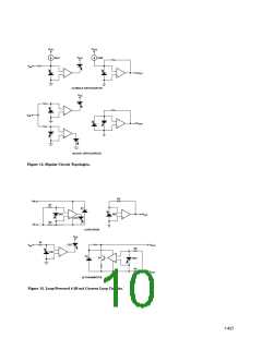
Remember, the circuit in
The relationship between the input
optical power and the output
current of a photodiode is very
linear. Therefore, by stabilizing
and linearizing IPD1, the light
output of the LED is also
Figure 12a is simplified in order
to explain the basic circuit opera-
tion. A practical circuit, more like
Figure 12b, will require a few
additional components to stabilize
the input part of the circuit, to
limit the LED current, or to
The operation of the basic circuit
may not be immediately obvious
just from inspecting Figure 12a,
stabilized and linearized. And
1-430

 AGILENT [ AGILENT TECHNOLOGIES, LTD. ]