LU6612
Data Sheet
July 2000
FASTCAT Single-FET for 10Base-T/100Base-TX
MII Station Management (continued)
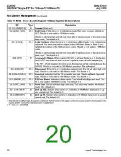
Table 17. MR28—Device-Specific Register 1 (Status Register) Bit Descriptions
Bit1
Type2
Description
28.15:9 (R28[15:9])
28.8 (BAD_FRM)
R
Unused. Read as 0.
R/LH Bad Frame. If this bit is a 1, it indicates a packet has been received without an
SFD. This bit is only valid in 10 Mbits/s mode.
This bit is latching high and will only clear after it has been read or the device has
been reset. The default is 0.
28.7 (CODE)
28.6 (APS)
R/LH Code Violation. When this bit is a 1, it indicates a Manchester code violation has
occurred. The error code will be output on the RXD lines. Refer to Table 1 for a
detailed description of the RXD pin error codes. This bit is only valid in 10 Mbits/s
mode.
This bit is latching high and will only clear after it has been read or the device has
been reset. The default is 0.
R
Autopolarity Status. When register 30, bit 3 is set and this bit is a 1, it indicates
the LU6612 has detected and corrected a polarity reversal on the twisted pair.
If the APF_EN bit (register 30, bit 3) is set, the reversal will be corrected inside the
LU6612. This bit is not valid in 100 Mbits/s operation. The default is 0.
28.5 (DISCON)
28.4 (UNLOCKED)
28.3 (RXERR_ST)
28.2 (FRC_JAM)
28.1 (LNK100UP)
28.0 (LNK10UP)
R/LH Disconnect. If this bit is a 1, it indicates a disconnect. This bit will latch high until
read. This bit is only valid in 100 Mbits/s mode. The default is 0.
R/LH Unlocked. Indicates that the TX scrambler lost lock. This bit will latch high until
read. This bit is only valid in 100 Mbits/s mode. The default is 0.
R/LH RX Error Status. Indicates a false carrier. This bit will latch high until read. This
bit is only valid in 100 Mbits/s mode. The default is 0.
R/LH Force Jam. This bit will latch high until read. This bit is only valid in 100 Mbits/s
mode. The default is 0.
R
R
Link Up 100. This bit, when set to a 1, indicates a 100 Mbits/s transceiver is up
and operational. The default is 0.
Link Up 10. This bit, when set to a 1, indicates a 10 Mbits/s transceiver is up and
operational. The default is 0.
1. Note that the format for the pin descriptions is as follows: the first number is the register number, the second number is the bit position in the
register, and the name of the instantiated pad is in capital letters.
2. R = read, LH = latched high.
20
Lucent Technologies Inc.

 AGERE [ AGERE SYSTEMS ]