ADV7180
Bits (Shading Indicates Default
State)
Comments
LQFP-64 LFCSP-40
Subaddress Register
Bit Description
Notes
7
6
5
4
3
2
0
0
0
0
1
1
1
1
1
0
0
1
1
0
0
1
1
0
0
1
0
1
0
1
0
1
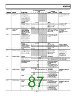
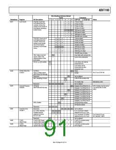
0x51
Lock Count
CIL[2:0]. Count into
lock determines the
number of lines the
system must remain in
lock before showing a
locked status.
1 line of video
2 lines of video
5 lines of video
10 lines of video
100 lines of video
500 lines of video
1000 lines of video
100,000 lines of video
1 line of video
COL[2:0]. Count out of
lock determines the
number of lines the
system must remain
out-of-lock before
showing a lost-locked
status.
0
0
0
0
1
1
1
1
0
0
1
1
0
0
1
1
0
1
0
1
0
1
0
1
2 lines of video
5 lines of video
10 lines of video
100 lines of video
500 lines of video
1000 lines of video
100,000 lines of video
Over field with vertical info
Line-to-line evaluation
SRLS. Select raw lock
signal. Selects the
determination of the
lock status.
0
1
FSCLE. FSC lock enable.
0
1
Lock status set only by
horizontal lock
Lock status set by
horizontal lock and
subcarrier lock
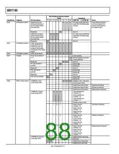
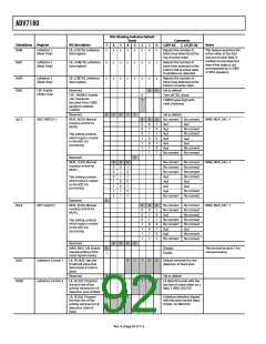
0x58
VSYNC/FIELD Pin
Control
VS/FIELD.
Vsync or field output.
ADV7180 LFCSP-40 only.
0
1
FIELD
Pin 37 on LFCSP-40
Mandatory write
VSYNC
Reserved.
0
Set to default
ADC Sampling Control.
0
1
CVBS/YPrPb modes only
Y/C mode only
Reserved.
0
0
0
0
0
Set to default
0x59
General-Purpose
Outputs
GPO[3:0].
ADV7180 LQFP-64 only.
0
1
Outputs 0 to GPO0, Pin 13
Outputs 1 to GPO0, Pin 13
Outputs 0 to GPO1, Pin 12
Outputs 1 to GPO1, Pin 12
Outputs 0 to GPO2, Pin 56
Outputs 1 to GPO2, Pin 56
Outputs 0 to GPO3, Pin 55
Outputs 1 to GPO3, Pin 55
GPO[3:0] three-stated
GPO[3:0] enabled
GPO_Enable must be set to
1 for these bits to take
effect
0
1
0
1
0
1
GPO_Enable.
0
1
Reserved.
Reserved.
0
0
0
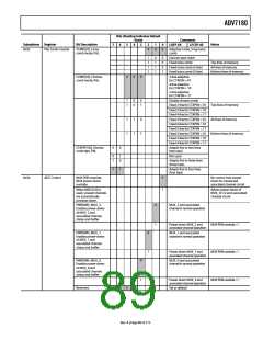
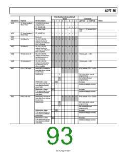
0x8F
Free-Run Line
Length 1
0
0
0
0
Set to default
LLC_PAD_SEL[2:0].
Enables manual
selection of clock
for LLC1 pin.
0
1
0
0
0
1
LLC1 (nominal 27 MHz)
selected out on LLC1 pin
LLC2 (nominal 13.5 MHz)
selected out on LLC1 pin
For 16-bit 4:2:2 out,
OF_SEL[3:0] = 0010
Reserved.
0
x
Set to default
0x99
0x9A
CCAP1
(Read Only)
CCAP1[7:0] Closed
caption data register.
x
x
x
x
x
x
x
x
x
x
x
x
x
x
CCAP1[7] contains parity
bit for Byte 0
CCAP2
CCAP2[7:0] Closed
caption data register.
x
CCAP2[7] contains parity
bit for Byte 0
(Read Only)
Rev. A | Page 91 of 112

 ADI [ ADI ]