ADV7180
Bits (Shading Indicates Default
State)
Comments
LQFP-64 LFCSP-40
Subaddress Register
Bit Description
Notes
7
6
5
4
3
2
1
0
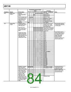
0x2D
Chroma Gain
Control 1
CMG[11:8]/CG[11:8]. In
manual mode, the
0
1
0
0
CAGC[1:0] settings decide
in which mode CMG[11:0]
operates
chroma gain control can
be used to program a
desired manual chroma
gain. In auto mode, it can
be used to read back the
current gain value.
Reserved.
1
0
1
0
Set to 1
CAGT[1:0]. Chroma
automatic gain timing
allows adjustment of
the chroma AGC
0
0
1
1
0
0
1
0
1
0
Slow (TC = 2 sec)
Medium (TC = 1 sec)
Fast (TC = 0.2 sec)
Adaptive
Has an effect only if
CAGC[1:0] is set to
autogain (10)
tracking speed.
0x2E
0x2F
Chroma Gain
Control 2
CMG[7:0]/CG[7:0].
Chroma manual gain
lower eight bits. See
CMG[11:8]/CG[11:8] for
description.
0
x
0
x
0
x
0
x
CMG[11:0] = 750d; gain is 1
in NTSC. CMG[11:0] = 741d;
gain is 1 in PAL
Min value is 0 dec
(G = 1/1000)
Max value is 3750 dec
(Gain = 5)
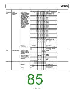
Luma Gain Control 1
LMG[11:8]/LG[11:8]. In
manual mode, luma gain
control can be used to
program a desired
LAGC[1:0] settings decide
in which mode LMG[11:0]
operates
manual chroma gain. In
auto mode, it can be
used to read back the
actual gain value used.
Reserved.
1
x
1
x
Set to 1
LAGT[1:0]. Luma
automatic gain timing
allows adjustment of
the luma AGC tracking
speed.
0
0
1
1
x
0
1
0
1
x
Slow (TC = 2 sec)
Medium (TC = 1 sec)
Fast (TC = 0.2 sec)
Adaptive
Only has an effect if
LAGC[1:0] is set to auto
gain (001, 010, 011,or 100)
0x30
0x31
Luma Gain Control 2
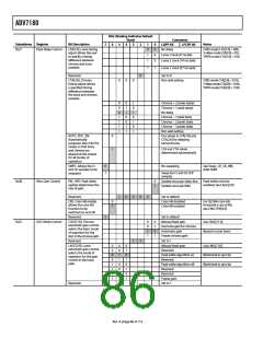
VS/FIELD Control 1
LMG[7:0]/LG[7:0]. Luma
manual gain lower eight
bits. See LMG[11:8]/
x
x
x
x
LMG[11:0] = 1600d;
gain is 1 in NTSC
LMG[11:0] = 1630d;
gain is 1 in PAL
Minimum value
NTSC 2048 (G = 0.5)
PAL 2048 (G = 0.5)
Maximum value
NTSC 4095 (G = 2)
PAL 4095 (G = 2)
LG[11:8] for description.
Reserved.
0
1
0
Set to default
HVSTIM. Selects where
within a line of video
the VS signal is asserted.
0
1
Start of line relative to HSE
Start of line relative to HSB
HSE = Hsync end
HSB = Hsync begin
NEWAVMODE. Sets the
EAV/SAV mode.
0
1
EAV/SAV codes generated
to suit Analog Devices
encoders
Manual VS/FIELD position
controlled by the 0x32, 0x33,
and 0xE5 to 0xEA registers
Reserved.
Reserved.
VSBHE.
0
0
0
0
Set to default
Set to default
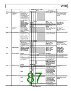
0x32
VS/FIELD Control 2
0
0
0
0
1
NEWAVMODE bit must be
set high
0
1
VS goes high in the middle
of the line (even field)
VS changes state at the
start of the line (even field)
VSBHO.
0
1
VS goes high in the middle
of the line (odd field)
VS changes state at the
start of the line (odd field)
0x33
VS/FIELD Control 3
Reserved.
VSEHE.
0
0
0
1
0
0
Set to default
0
1
VS goes low in the middle
of the line (even field)
NEWAVMODE bit must be
set high
VS changes state at the
start of the line (even field)
VSEHO.
0
1
VS goes low in the middle
of the line (odd field)
VS changes state at the
start of the line odd field
Rev. A | Page 87 of 112

 ADI [ ADI ]