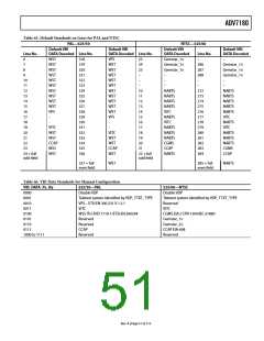
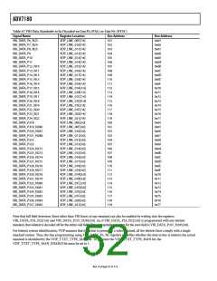
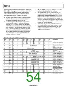
ADV7180
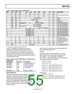
Table 71. Ancillary Data in Byte Output Format1
Byte
B9
B8
B7
B6
B5
0
B4
0
B3
0
B2
0
B1
0
1
1
0
0
0
0
0
0
0
0
0
0
0
0
.
B0
0
1
1
0
0
0
0
0
0
0
0
0
0
0
0
.
Description
0
0
0
0
0
Ancillary data preamble.
1
1
1
1
1
1
1
1
1
2
1
1
1
1
1
1
1
1
3
EP
EP
EP
EP
EP
EP
EP
0
I2C_DID6_2[4:0]
I2C_SDID7_2[5:0]
DC[4:0]
DID.
EP
EP
EP
EP
EP
EP
EP
4
SDID.
5
0
Data count.
6
padding[1:0]
VBI_DATA_STD[3:0]
Line_number[9:5]
ID0 (User Data-Word 1).
ID1 (User Data-Word 2).
ID2 (User Data-Word 3).
ID3 (User Data-Word 4).
ID4 (User Data-Word 5).
ID5 (User Data-Word 6).
ID6 (User Data-Word 7).
ID7 (User Data-Word 8).
ID8 (User Data-Word 9).
7
0
8
Even_Field
0
Line_number[4:0]
9
0
0
0
VDP_TTXT_TYPE[1:0]
10
11
12
13
14
.
VBI_WORD_1[7:0]
VBI_WORD_2[7:0]
VBI_WORD_3[7:0]
VBI_WORD_4[7:0]
VBI_WORD_5[7:0]
.
.
.
.
.
.
.
.
Pad 0x200. These
.
.
.
.
.
.
.
.
.
.
.
padding words may be
present depending on
ancillary data type. User
data-word xx.
.
.
.
.
.
.
.
.
.
.
.
n − 3
n − 2
n − 1
1
1
B8
0
0
0
0
0
0
0
0
0
0
0
0
0
0
0
0
0
0
0
0
Checksum
CS (checksum word).
1 This mode does not fully comply with ITU-R BT.1364.
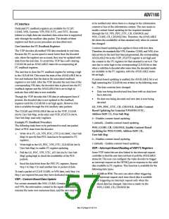
Table 73 shows the framing code and its valid length for VBI
data standards supported by VDP.
Structure of VBI Words in Ancillary Data Stream
Each VBI data standard has been split into a clock-run-in
(CRI), a framing code (FC), and a number of data bytes (n).
The data packet in the ancillary stream includes only the FC
and data bytes. Table 72 shows the format of the VBI_WORD_x
in the ancillary data stream.
Example
For teletext (B-WST), the framing code byte is 11100100
(0xE4), with bits shown in the order of transmission. For
VBI_WORD_1 = 0x27, VBI_WORD_2 = 0x00, and
VBI_WORD_3 = 0x00 translated into UDWs in the ancillary
data stream for nibble mode is as follows:
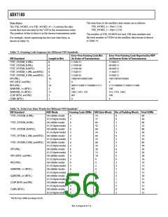
Table 72. Structure of VBI Data-Words in Ancillary Stream
Ancillary Data
UDW5 [5:2] = 0010
Byte Number
VBI_WORD_1
VBI_WORD_2
VBI_WORD_3
VBI_WORD_4
…
Byte Type
FC0
FC1
FC2
DB1
Description
UDW6 [5:2] = 0111
Framing code [23:16]
Framing code [15:8]
Framing code [7:0]
1st data byte
UDW7 [5:2] = 0000 (undefined bits set to 0)
UDW8 [5:2] = 0000 (undefined bits set to 0)
UDW9 [5:2] = 0000 (undefined bits set to 0)
UDW10 [5:2] = 0000 (undefined bits set to 0)
…
DBn
…
VBI_WORD_N + 3
Last (nth) data byte
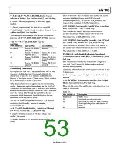
VDP Framing Code
For byte mode:
UDW5 [9:2] = 0010_0111
The length of the actual framing code depends on the VBI data
standard. For uniformity, the length of the framing code
reported in the ancillary data stream is always 24 bits. For
standards with a smaller framing code length, the extra LSB bits
are set to 0. The valid length of the framing code can be
decoded from the VBI_DATA_STD bit available in ID0
(UDW 1). The framing code is always reported in the inverse-
transmission order.
UDW6 [9:2] = 0000_0000 (undefined bits set to 0)
UDW7 [9:2] = 0000_0000 (undefined bits set to 0)
Rev. A | Page 55 of 112

 ADI [ ADI ]