ADM3485E
Four severity levels are defined in terms of an open-circuit volt-
age as a function of installation environment. The installation
environments are defined as
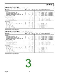
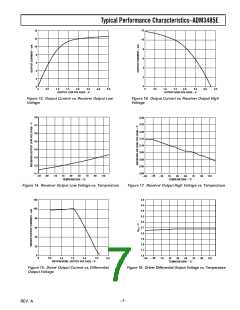
100%
90%
1. Well-Protected
2. Protected
3. Typical Industrial
4. Severe Industrial
36.8%
10%
V
t
TIME t
tDL
tRL
300ms
16ms
Figure 21. Human Body Model Current Waveform
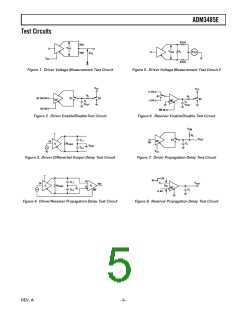
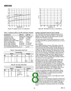
V
5ns
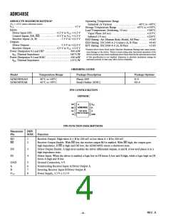
Table IV. ESD Test Results
50ns
ESD Test Method
I-O Pins
t
IEC1000-4-2: Contact
8 kV
0.2/0.4ms
100%
90%
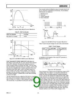
Figure 23. IEC1000-4-4 Fast Transient Waveform
Table V shows the peak voltages for each of the environments.
Table V. Peak Voltages
Level
V PEAK (kV) PSU
VPEAK (kV) I-O
1
2
3
4
0.5
1
2
0.25
0.5
1
10%
0.1 TO 1ns
4
2
TIME
t
30ns
60ns
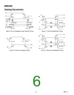
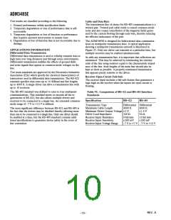
A simplified circuit diagram of the actual EFT generator is
illustrated in Figure 24.
Figure 22. IEC1000-4-2 ESD Current Waveform
FAST TRANSIENT BURST IMMUNITY (IEC1000-4-4)
IEC1000-4-4 (previously 801-4) covers electrical fast-transient/
burst (EFT) immunity. Electrical fast transients occur as a
result of arcing contacts in switches and relays. The tests simu-
late the interference generated when, for example, a power relay
disconnects an inductive load. A spark is generated due to the
well known back EMF effect. In fact, the spark consists of a
burst of sparks as the relay contacts separate. The voltage ap-
pearing on the line, therefore, consists of a burst of extremely
fast transient impulses. A similar effect occurs when switching
on fluorescent lights.
C
D
R
R
L
HIGH
VOLTAGE
SOURCE
M
C
50ꢀ
OUTPUT
C
Z
C
S
Figure 24. EFT Generator
These transients are coupled onto the signal lines using an EFT
coupling clamp. The clamp is 1 m long and completely sur-
rounds the cable, providing maximum coupling capacitance
(50 pF to 200 pF typ) between the clamp and the cable. High
energy transients are capacitively coupled onto the signal lines.
Fast rise times (5 ns) as specified by the standard result in very
effective coupling. This test is very severe since high voltages are
coupled onto the signal lines. The repetitive transients can often
cause problems, where single pulses do not. Destructive latchup
may be induced due to the high energy content of the transients.
Note that this stress is applied while the interface products are
powered up and are transmitting data. The EFT test applies
hundreds of pulses with higher energy than ESD. Worst case
transient current on an I-O line can be as high as 40 A.
The fast transient burst test, defined in IEC1000-4-4, simulates
this arcing and its waveform is illustrated in Figure 23. It con-
sists of a burst of 2.5 kHz to 5 kHz transients repeating at
300 ms intervals. It is specified for both power and data lines.
REV. A
–9–

 ADI [ ADI ]