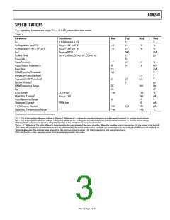
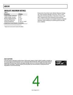
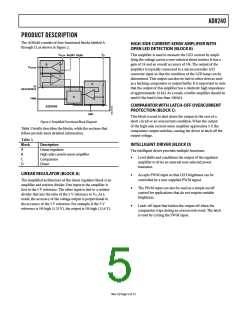
AD8240
CONTROLLING THE LED LAMP
The LEDs are turned on and off depending on the CMOS
compatible digital voltage level present at the PWM pin (Pin 3).
This voltage can be continuous for a simple on/off function, or
PWM for dimming control. The PWM frequency should be less
than 500 Hz with a range from 5% to 100%. Typical values are
5% for running and 95% for braking.
To determine if the load is correct, the voltage at VSENSE should
be as follows during full power operation:
500 mA × 0.4 Ω × 24 V/V = 4.8 V
If there is a partial LED failure, VSENSE drops in proportion to the
quantity of the failure. For example, if 25% of the LEDs fail, the
voltage drops by 25%.
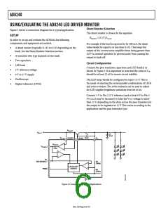
USING/EVALUATING THE VSENSE OUTPUT
Important: The output impedance of VSENSE is approximately
10 kΩ. Because of this, it may be necessary to buffer the output
in order to drive a load of less than 100 kΩ. An oscilloscope,
micro-controller A/D converter, or DVM may be used to
accurately measure the voltage at the VSENSE pin.
If there is a short to ground, VSENSE is near 0 V because the
output is latched off and no current is flowing.
Using/Evaluating the Short-Circuit Protection Feature
If there is a short or an overload condition, the voltage at
V
SENSE falls close to zero, and the output shuts down
The VSENSE output is used to detect a partial LED failure, or an
overcurrent condition. The voltage present at VSENSE is propor-
tional to the current through the load with the equation
(the transistor driver shuts off). This resets when the PWM
voltage is brought low and then high again. If the condition
persists, the AD8240 attempts to drive the output to 12 V and
then immediately shuts down. If a PWM voltage is used, the
AD8240 attempts to start after each PWM cycle.
I
LOAD = (VSENSE/24)/RSHUNT
Selection of the shunt resistor can be found by manipulating this
equation. For example
This can be simulated by increasing the load so the voltage at
VSENSE slightly exceeds 5 V. When this happens, the output shuts
VSENSE = ILOAD × RSHUNT
Expected Load = 500 mA
RSHUNT = 0.4 Ω
down, and the VSENSE voltage is close to 0 V.
Rev. 0 | Page 7 of 12

 ADI [ ADI ]