AD8240
PRODUCT DESCRIPTION
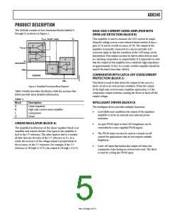
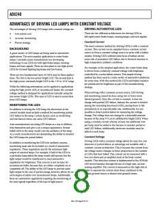
The AD8240 consists of four functional blocks labeled A
through D, as shown in Figure 2.
HIGH-SIDE CURRENT-SENSE AMPLIFIER WITH
OPEN LED DETECTION (BLOCK B)
VPLUS
VO
This amplifier is used to measure the LED current by ampli-
fying the voltage across a user-selected shunt resistor. It has a
gain of 24 and an overall accuracy of 5%. The output of the
amplifier is typically connected to a microcontroller A/D
converter input so that the condition of the LED lamp can be
determined. This output can also be tied to other devices such
as a latching comparator or output buffer. It is important to note
that the output of this amplifier has a relatively high impedance
of approximately 10 kΩ. As a result, a buffer amplifier should be
used if the load is less than 100 kΩ.
SHUNT BASE
B
VSENSE
C
A
5V
REFERENCE
D
PWM
COMPARATOR WITH LATCH-OFF OVERCURRENT
PROTECTION (BLOCK C)
AD8240
GND
This block is used to shut down the output in the case of a
short circuit or an overcurrent condition. When the output
of the high-side current-sense amplifier approaches 5 V, the
comparator output switches, causing the driver to latch off the
output voltage.
Figure 2. Simplified Functional Block Diagram
Table 3 briefly describes the blocks, while the sections that
follow provide more detailed information.
Table 3.
Block
Description
INTELLIGENT DRIVER (BLOCK D)
A
B
C
D
Linear regulator
High-side current-sense amplifier
Comparator
The intelligent driver provides multiple functions:
•
Level shifts and conditions the output of the regulator
amplifier to drive an external user-selected power
transistor.
Driver
LINEAR REGULATOR (BLOCK A)
•
•
Accepts PWM input so that LED brightness can be
controlled by a user-supplied PWM signal.
The simplified architecture of the linear regulator block is an
amplifier and resistor divider. One input to the amplifier is
tied to the 5 V reference. The other input is tied to a resistor
divider that sets the ratio of the 5 V reference to VO. As a
result, the accuracy of the voltage output is proportional to
the accuracy of the 5 V reference. For example, if the 5 V
reference is 5% high (5.25 V), the output is 5% high (12.6 V).
The PWM input can also be used as a simple on/off
control for applications that do not require variable
brightness.
•
Latch-off input that latches the output off when the
comparator trips during an overcurrent event. The latch
is reset by cycling the PWM input.
Rev. 0 | Page 5 of 12

 ADI [ ADI ]