Data Sheet
AD7904/AD7914/AD7924
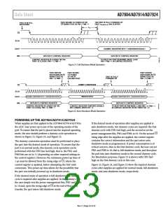
PART BEGINS TO POWER UP ON
CS RISING EDGE AS PM1 = PM0 = 1
THE PART IS FULLY POWERED UP
ONCE tPOWER UP HAS ELAPSED
PART IS IN FULL
SHUTDOWN
t12
CS
1
14
16
1
14
16
SCLK
DOUT
DIN
CHANNEL IDENTIFIER BITS + CONVERSION RESULT
DATA IN TO CONTROL REGISTER
DATA IN TO CONTROL REGISTER
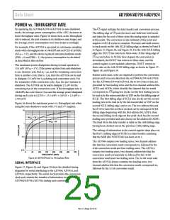
CONTROL REGISTER IS LOADED ON THE
FIRST 12 CLOCKS. PM1 = 1, PM0 = 1
TO KEEP THE PART IN NORMAL MODE, LOAD
PM1 = PM0 = 1 IN CONTROL REGISTER
Figure 21. Full Shutdown Mode Operation
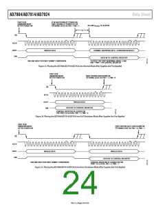
PART ENTERS
PART BEGINS
TO POWER
UP ON CS
PART ENTERS
SHUTDOWN ON CS
RISING EDGE AS
PM1 = 0, PM0 = 1
SHUTDOWN ON CS
RISING EDGE AS
PM1 = 0, PM0 = 1
PART IS FULLY
POWERED UP
FALLING EDGE
DUMMY CONVERSION
CS
1
12
16
1
12
16
1
12
16
SCLK
DOUT
CHANNEL IDENTIFIER BITS + CONVERSION RESULT
DATA IN TO CONTROL REGISTER
CHANNEL IDENTIFIER BITS + CONVERSION RESULT
DATA IN TO CONTROL REGISTER
INVALID DATA
DIN
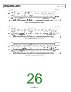
CONTROL REGISTER IS LOADED ON THE
FIRST 12 CLOCKS, PM1 = 0, PM0 = 1
CONTROL REGISTER CONTENTS SHOULD
NOT CHANGE, WRITE BIT = 0
TO KEEP PART IN THIS MODE, LOAD PM1 = 0, PM0 = 1
IN CONTROL REGISTER OR SET WRITE BIT = 0
Figure 22. Auto Shutdown Mode Operation
POWERING UP THE AD7904/AD7914/AD7924
When supplies are first applied to the AD7904/AD7914/AD7924,
the ADC may power up in any of the operating modes of the
part. To ensure that the part is placed into the required operating
mode, the user should perform a dummy cycle operation as
shown in Figure 23, Figure 24, and Figure 25.
If the desired mode of operation after supplies are applied is
auto shutdown mode, two dummy cycles are required: the first
dummy cycle with DIN tied high, and the second to set the
CS
power management bits, PM1 and PM0, to 01. On the second
rising edge after the supplies are applied, the control register
contains the correct information and the part enters auto
shutdown mode as programmed. If power consumption is of
critical concern, then in the first dummy cycle, the user can set
PM1 and PM0 to 10, that is, full shutdown mode, and then place
the part into auto shutdown mode in the second dummy cycle.
For illustration purposes, Figure 25 is shown with DIN tied
high on the first dummy cycle in this case.
The dummy conversion operation must be performed to place
the part into the desired mode of operation. To ensure that the
part is in normal mode, this dummy cycle operation can be
performed with the DIN line tied high, that is, the PM1 and
PM0 bits are set to 11 (depending on other required settings in
the control register). However, the minimum power-up time of
CS
1 µs must be allowed from the rising edge of , where the
control register is updated, before attempting the first valid
conversion. This power-up time allows for the possibility that
the part was initially powered up in shutdown mode.
Figure 23, Figure 24, and Figure 25 show the required dummy
cycles after supplies are applied for normal mode, full shutdown
mode, and auto shutdown mode, respectively.
If the desired mode of operation is full shutdown, one dummy
cycle is required after supplies are applied. In this dummy cycle,
the user simply sets the power management bits, PM1 and PM0,
CS
to 10 and, upon the rising edge of
at the end of that serial
transfer, the part enters full shutdown mode.
Rev. C | Page 23 of 32

 ADI [ ADI ]