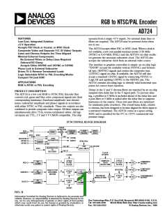
(Unless otherwise noted, VS = +5, TA = +25؇C, using FSC synchronous clock. All loads are
150 ⍀ ؎ 5% at the IC pins. Outputs are measured at the 75 ⍀ reverse terminated load.)
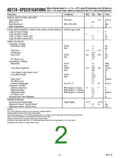
AD724–SPECIFICATIONS
Parameter
Conditions
Min Typ Max
Units
SIGNAL INPUTS (RIN, GIN, BIN)
Input Amplitude
Full Scale
714
mV p-p
V
MΩ
pF
Black Level1
0.8
Input Resistance2
Input Capacitance
RIN, GIN, BIN
1
5
LOGIC INPUTS (HSYNC, VSYNC, FIN, ENCD, STND, SELECT) CMOS Logic Levels
Logic LO Input Voltage
1
V
Logic HI Input Voltage
2
V
Logic LO Input Current (DC)
Logic HI Input Current (DC)
<1
<1
µA
µA
VIDEO OUTPUTS3
Luminance (LUMA)
Roll-Off @ 5 MHz
NTSC
PAL
–7
–6
–3
±0.3
286
300
1.3
dB
dB
%
Gain Error
Nonlinearity
Sync Level
–15
243
+15
329
%
NTSC
PAL
mV
mV
V
DC Black Level
Chrominance (CRMA)
Bandwidth
NTSC
PAL
NTSC
PAL
3.6
4.4
249
288
±5
2.51
2.28
±3
MHz
MHz
mV p-p
mV
%
µs
µs
Degrees
V
Color Burst Amplitude
170
330
Color Signal to Burst Ratio Error4
Color Burst Width
NTSC
PAL
Phase Error5
DC Black Level
2.0
15
Chroma Feedthrough
Composite (COMP)
Absolute Gain Error
Differential Gain
Differential Phase
DC Black Level
R, G, B = 0
40
5
mV p-p
With Respect to Luma
With Respect to Chroma
With Respect to Chroma
–5
±1
0.5
2.0
1.5
0
%
%
Degrees
V
Chroma/Luma Time Alignment
ns
POWER SUPPLIES
Recommended Supply Range
Quiescent Current—Encode Mode6
Quiescent Current—Power Down
Single Supply
+4.75
+5.25
42
V
mA
mA
33
1
NOTES
1R, G, and B signals are inputted via an external ac coupling capacitor.
2Except during dc restore period (back porch clamp).
3All outputs measured at a 75 Ω reverse-terminated load; ac voltages at the IC output pins are twice those specified here.
4Ratio of chroma amplitude to burst amplitude, difference from ideal.
5Difference between ideal color-bar phases and the actual values.
6Driving the logic inputs with VOH < 4 V will increase static supply current approximately 150 µA per input.
Specifications are subject to change without notice.
–2–
REV. B

 ADI [ ADI ]