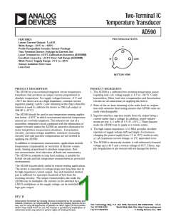
AD590
T he 590H has 60 µ inches of gold plating on its Kovar leads and
Kovar header. A resistance welder is used to seal the nickel cap
to the header. T he AD590 chip is eutectically mounted to the
header and ultrasonically bonded to with 1 MIL aluminum
wire. Kovar composition: 53% iron nominal; 29% ±1% nickel;
17% ± 1% cobalt; 0.65% manganese max; 0.20% silicon max;
0.10% aluminum max; 0.10% magnesium max; 0.10% zirco-
nium max; 0.10% titanium max; 0.06% carbon max.
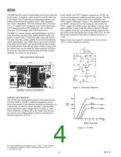
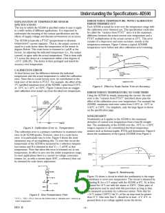
In the AD590, this PT AT voltage is converted to a PT AT cur-
rent by low temperature coefficient thin-film resistors. T he total
current of the device is then forced to be a multiple of this
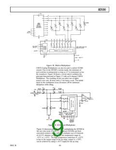
PT AT current. Referring to Figure 1, the schematic diagram of
the AD590, Q8 and Q11 are the transistors that produce the
PT AT voltage. R5 and R6 convert the voltage to current. Q10,
whose collector current tracks the colletor currents in Q9 and
Q11, supplies all the bias and substrate leakage current for the
rest of the circuit, forcing the total current to be PT AT . R5 and
R6 are laser trimmed on the wafer to calibrate the device at
+25°C.
T he 590F is a ceramic package with gold plating on its Kovar
leads, Kovar lid, and chip cavity. Solder of 80/20 Au/Sn com-
position is used for the 1.5 mil thick solder ring under the lid.
T he chip cavity has a nickel underlay between the metalization
and the gold plating. T he AD590 chip is eutectically mounted
in the chip cavity at 410°C and ultrasonically bonded to with 1
mil aluminum wire. Note that the chip is in direct contact with
the ceramic base, not the metal lid. When using the AD590 in
die form, the chip substrate must be kept electrically isolated,
(floating), for correct circuit operation.
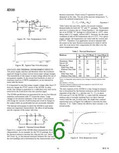
Figure 2 shows the typical V–I characteristic of the circuit at
+25°C and the temperature extremes.
METALIZATIO N D IAGRAM
Figure 1. Schem atic Diagram
CIRCUIT D ESCRIP TIO N1
T he AD590 uses a fundamental property of the silicon transis-
tors from which it is made to realize its temperature propor-
tional characteristic: if two identical transistors are operated at a
constant ratio of collector current densities, r, then the differ-
ence in their base-emitter voltage will be (kT /q)(In r). Since
both k, Boltzman’s constant and q, the charge of an electron,
are constant, the resulting voltage is directly proportional to
absolute temperature (PT AT ).
Figure 2. V–I Plot
1For a more detailed circuit description see M.P. T imko, “A T wo-T erminal
IC T emperature T ransducer,” IEEE J. Solid State Circuits, Vol. SC-11,
p. 784-788, Dec. 1976.
REV. B
–4–

 ADI [ ADI ]