AD5399
Shutdown Function
The AD5399 shutdown function allows both DACs to be
shutdown simultaneously. However, the Aꢀ and SD bits work in
tandem, and the Aꢀ logic state must be the same for shutdown
activation and deactivation (see Table 7).
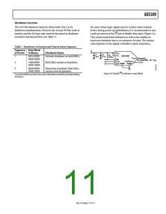
For users whose logic signals may be in three-state (random
levels) during power-up initialization, it is recommended to put
a pull-up resistor at the pin to disable chip select (Figure 24).
This avoids inadvertent shutdown as well as the inability to
deactivate shutdown due to an unknown Aꢀ state. The resistor
value depends on the digital controller’s output impedance.
CS
Table 7. Shutdown Activation and Deactivation Sequence.
Sequence Data-Word
5V
V
of Events
in Binary
Shutdown Status
DD
C1
10µF
C2
0.1µF
R1
300kΩ
V
TP
AD5399
1
0X10 XXXX
XXXX XXXX
Activate shutdown on both DACs.
V
OUTA
CS
CLK
SDI
(D–2048)/4096 × 4V + V
BZ
V
(V
)
BZ REF
2V
2
3
1X00 XXXX
XXXX XXXX
0X00 XXXX
XXXX XXXX
Both DACs remain at shutdown.
DGND AGND
Deactivate shutdown. Both DACs
resume normal operation.
CS
Figure 24. Disable for Random Logic Mode
The A0 bit (MSB) must be in the same state when activating and deactivating
shutdown.
Rev. D | Page 11 of 12

 ADI [ ADI ]