ACE24LC02/04/08/16
Two-wire Serial EEPROM
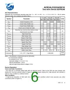
AC Characteristics
Applicable over recommended operating range from: TA = -40℃ to +85℃, VCC = +1.7V to +3.6V, CL = 100 pF (unless
otherwise noted). Test conditions are listed in Note 2.
1.7-volt
2.5-volt
3.6-volt
Symbol
Parameter
Units
Min Max Min Max Min Max
fSCL
TLOW
THIGH
TAA
Clock Frequency, SCL
Clock Pulse Width Low
Clock Pulse Width High
Clock Low to Data Out Valid
Time the bus must be free before a new
transmission can Start
Start Hold Time
400
1000
1000 kHz
1.3
0.6
0.4
0.4
0.4
0.4
µs
µs
0.05 0.9 0.05 0.55 0.05 0.55
µs
1
TBUF
1.2
0.5
0.5
µs
THD.STA
TSU.STA
THD.DAT
TSU.DAT
TR
0.6
0.6
0
0.25
0.25
0
0.25
0.25
0
µs
µs
Start Setup Time
Data In Hold Time
µs
Data In Setup Time
100
100
100
ns
Inputs Rise Time
0.3
0.3
0.3
µs
TF
Inputs Fall Time
300
100
100
ns
TSU.STO
TDH
Stop Setup Time
0.6
50
0.25
50
0.25
50
µs
Data Out Hold Time
Write Cycle Time
ns
TWR
5
5
5
ms
Write
Cycles
Endurance1
3.3V, 25℃, Page Mode
1,000,000
Notes:1. This parameter is characterized and not 100% tested.
2.AC measurement conditions:
RL (connects to Vcc): 1.3kΩ
Input pulse voltages: 0.3 Vcc to 0.7 Vcc
Input rise and fall times: ≦50 ns
Input and output timing reference voltages: 0.5Vcc
Device Operation
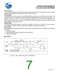
Clock and Data Transitions:
The SDA pin is normally pulled high with an external device. Data on the SDA pin may change only
during SCL low time periods (refer to Figure 4). Data changes during SCL high periods will indicate a
start or stop condition as defined below.
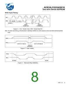
Start Condition:
A high-to-low transition of SDA with SCL high is a start condition which must precede any other
command (refer to Figure 5).
VER 1.6
6

 ACE [ ACE TECHNOLOGY CO., LTD. ]