BRIGHT
Microelectronics
Inc.
Preliminary BM29F040
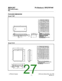
PACKAGE DIMENSIONS
32-pin P-DIP
Dimension in inches
Dimension in mm
Symbol
Min. Nom. Max. Min. Nom. Max.
5.33
0.210
A
A1
A
B
B
c
D
E
E1
e1
0.010
0.25
0.150 0.155 0.160 3.81
3.94
0.46
1.27
0.25
4.06
0.56
1.37
0.36
2
0.016 0.018
0.41
1.22
0.022
0.054
0.050
0.048
0.008
1
0.010 0.014 0.20
1.650 1.660
D
17
32
41.91 42.16
15.49
13.84 13.97 14.10
0.610
0.555
0.110
15.24
0.590 0.600
0.545 0.550
0.090 0.100
14.99
2.29
3.05
0
2.54
3.30
2.79
E1
0.120
0
0.140
15
0.130
3.56
15
L
a
17.02
0.630 0.650 0.670 16.00 16.51
0.085
eA
S
2.16
16
1
Notes:
E
S
1.Dimensions D Max. & S include mold flash or
tie bar burrs.
c
2.Dimension E1 does not include interlead flash.
2
A
A
L
A1
Base Plane
3.Dimensions D & E1 include mold mismatch and
.
are determined at the mold parting line.
4.Dimension B1 does not include dambar
protrusion/intrusion.
5.Controlling dimension: Inches
6.General appearance spec. should be based on
Seating Plane
B
e1
eA
a
B1
final visual inspection spec.
32-pin PLCC
Dimension in Inches
Dimension in mm
Symbol
Min. Nom. Max. Min. Nom. Max.
H E
E
0.140
3.56
A
A
A
b
b
c
D
E
e
G
G
H
H
L
y
0.020
0.105
0.026
0.016
0.008
0.547
0.447
0.044
0.490
0.390
0.585
0.485
0.075
0.50
2.67
1
4
30
1
32
0.110
0.028
0.018
0.010
0.550
0.450
0.050
0.51
0.115
0.032
0.022
0.014
0.553
0.453
0.056
0.530
0.430
0.595
0.495
0.095
0.004
2.80
0.71
0.46
0.25
13.97
11.43
1.27
12.9
2.93
0.81
2
1
0.66
0.41
0.56
5
29
0.20
0.35
13.89
11.35
1.12
14.05
11.51
1.42
12.45
9.91
13.46
10.92
15.11
12.57
2.41
D
D
G
0.410
0.590
0.49
10.41
14.99
12.45
2.29
E
D
E
D
H D
14.86
12.32
1.91
0.090
0.10
°
0
°
0
°
10
°
10
q
21
13
Notes:
1. Dimensions D & E do not include interlead flash.
2. Dimension b1 does not include dambar protrusion/intrusion.
3. Controlling dimension: Inches
14
c
20
4. General appearance spec. should be based on final
visual inspection sepc.
L
A2
A
q
e
1
b
A
b 1
Seating Plane
y
E
G
A Winbond Company
Publication Release Date: June 1999
Revision A1
- 27 -

 WINBOND [ WINBOND ]