THCV231-Q_THCV236-Q_Rev.2.60_E
Contents Page
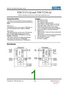
General Description .............................................................................................................................................. 1
Features.................................................................................................................................................................. 1
Block Diagram....................................................................................................................................................... 1
Pin Configuration.................................................................................................................................................. 4
Pin Description ...................................................................................................................................................... 5
Pin Description for THCV231-Q ........................................................................................................................ 5
Pin Description for THCV236-Q ........................................................................................................................ 6
Functional Overview........................................................................................................................................... 10
Functional Description........................................................................................................................................ 10
Internal Reference Output/Input Function (CAPOUT, CAPINA, CAPINP) ............................................ 10
Power Down (PDN1, PDN0, PDN)................................................................................................................. 11
Pre-emphasis and Drive Select Function (THCV231-Q only)..................................................................... 11
Permanent Clock Output (THCV236-Q only).............................................................................................. 11
Spread Spectrum Clock Generator (SSCG).................................................................................................. 12
Data Enable...................................................................................................................................................... 14
Hot-Plug Function........................................................................................................................................... 15
Lock Detect Function...................................................................................................................................... 15
Field BET Operation....................................................................................................................................... 16
Data Width and Frequency Range Select Function ..................................................................................... 18
Data Mapping .................................................................................................................................................. 18
2-wire serial I/F Mode..................................................................................................................................... 19
2-wire serial I/F Device ID setting ................................................................................................................ 19
2-wire serial I/F Clock Stretching ................................................................................................................. 19
Read/Write access to Sub-Link Master Register........................................................................................... 21
Read/Write access to Sub-Link Slave Register ............................................................................................. 22
Read/Write access to remote side 2-wire serial slave devices connected to Sub-Link Slave Device............ 24
GPIO.............................................................................................................................................................. 28
Interruption.................................................................................................................................................... 30
Register Map........................................................................................................................................................ 31
Absolute Maximum Ratings............................................................................................................................... 40
Recommended Operating Conditions................................................................................................................ 40
Electrical Specification........................................................................................................................................ 40
LVCMOS DC Specification .............................................................................................................................. 40
CML DC Specification...................................................................................................................................... 41
CML Bi-Directional DC Specification.............................................................................................................. 41
Copyright©2017 THine Electronics, Inc.
THine Electronics, Inc.
2/58
Security E

 THINE [ THINE ELECTRONICS, INC. ]