FEDL87V2107-01
OKI Semiconductor
ML87V2107
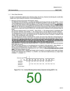
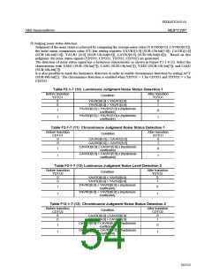
2.1.7 Noise Status Detection
In order to automatically optimize noise reduction setting, this IC has a function for detecting the overall video
sample noise status during the motionless vertical blanking period.
•
Detection of noise level (average and maximum values)
Set NRDTON (SUB:49h-bit[1]) = 1 to detect the blanking period noise level for one line (NDTC = 0) of a
vertical blanking period set by NRDTP[2:0](SUB:57h-bit[4:2]) and DTPSL (SUB:57h-bit[7]). Alternatively,
you can set the same register to detect the blanking noise (average and maximum values) for one line (NDTC
= 1) of the maximum noise level of multiple lines (maximum 8 lines not including valid lines) ending with line
NRDTP[2:0]. The detection of blanking period noise (average and maximum values) and the noise on the line
on which the average noise between fields for the valid data period is minimum can be performed frame by
frame.
The detection starting position is set in DTPSL. When DTPSL = 0, the starting position is immediately after
the end of the valid lines; when DTPSL = 1, the starting position is one line after the end of the valid lines.
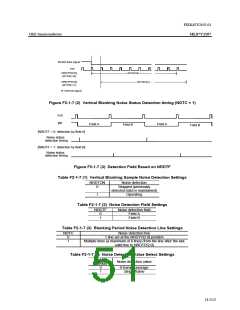
In a blanking period, one line is divided into two sections, the noise levels of the two sections are detected,
and the larger average noise value between the first 128 pixels and second 128 pixels is assumed as the
average value and maximum value of the line.
In a valid data period, one line is divided into four sections, the noise levels of the four 128-pixel periods are
detected, and the lowest average noise value is assumed as the average value and maximum value of the line.
For noise in a valid data period, this IC uses the noise level that is detected under the conditions where
the noise detection line slope is 1, the noise convergence line slope is -1, and the noise convergence level
is the one that is detected by the non-linear filter at twice the upper limit noise level.
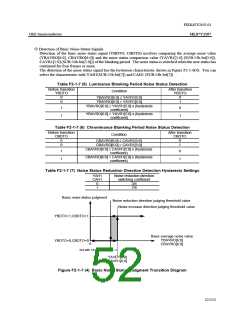
When NRDTON = 0, the final status data for NRDTON = 1 is preserved. Initially, the average and maximum
noise values are set at 0.
The fields for which detection is to be performed are set in NRDTF (SUB:49h-bit[5]). When NRDTF = 0,
field A vertical blanking period is set; when NRDTF = 1, field B vertical blanking period is set.
For detection of a noise level for a blanking period, the X addresses 304 to 311(A field) and 816 to 823(B
field) of the built-in memory are used.
By setting YNAMS (SUB:57-bit[0]) and CNAMS (SUB:57h-bit[1]), it is possible to select either an 8-frame
average of the detected noise (YNMAS = 0, CNAMS = 0) or the level of detected noise in a single frame
(YNMAS = 1, CNAMS = 1).
#Valid data signal
IHS
0
1
0
2
1
3
2
4
3
5
4
14
13
15
14
NRDTP[3:0]
(DTPSL=0)
5
15
NRDTP[3:0]
(DTPSL=1)
#: Internal signal
Figure F2-1-7 (1) Vertical Blanking Noise Status Detection timing (NDTC = 0)
50/152

 OKI [ OKI ELECTRONIC COMPONETS ]