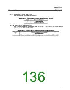
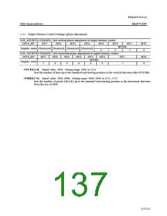
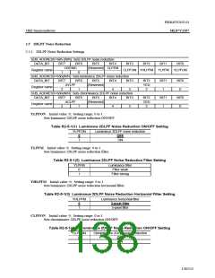
FEDL87V2107-01
OKI Semiconductor
ML87V2107
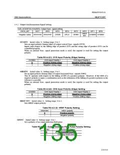
2.4.2 Output Synchronization Signal Setting
SUB_ADDRESS=61h(W/R): Output Sync. signal setting
DATA_BIT
BIT7
BIT6
BIT5
BIT4
BIT3
BIT2
BIT1
BIT0
HREF
INV
(Reserved) (Reserved)
Register name
OVEM
OFLS
OFINV
OHSINV OVSINV
OVSINV Initial value: 0; Setting range: 0 to 1
Sets an input polarity (timing edge) of output vertical Sync. signals (OVS).
Inputs with respect to the falling edge of positive OVS and the rising edge of positive OVS can be
controlled properly.
When an internal Sync. signal generation mode is used, this register is used for setting the output
polarity.
Table-R2-4-2(1) OVS Input Polarity (Edge) Setting
OVSINV
OVS Input Polarity 1
Positive (falling edge)
Negative (rising edge)
OVS Input Polarity 2
Negative (falling edge)
Positive (rising edge)
0
1
OHSINV Initial value: 0; Setting range: 0 to 1
Set an input polarity (timing edge) of output horizontal Sync. signals (OHS).
This IC operates with respect to the falling of IHS of a positive polarity. However, if the OHS of a
negative polarity is input, a combination such as the utilization of the falling of a positive polarity as the
reference is possible.
When an internal Sync. signal generation mode is used, this register is used for setting the output
polarity.
Table-R2-4-2(2) OHS Input Polarity (Edge) Setting
OHSINV
OHS Input Polarity 1
Positive (rising edge)
Negative (falling edge)
OHS Input Polarity 2
Negative (rising edge)
Positive (falling edge)
0
1
HREF INV Initial value: 0; Setting range: 0 to 1
Sets HREF output polarity.
Table R2-4-2 (3) HREF Polarity Setting
HREFINV
HREF polarity
0
Positive polarity
1
Negative polarity
OFINV Initial value: 0; Setting range: 0 to 1
Set a polarity of an output detection field pulse.
Table R2-4-2(4) Output Detection Field Pulse Polarity Setting
OFINV
Detection field pulse
Checking result
0
1
Checking result inverted
135/152

 OKI [ OKI ELECTRONIC COMPONETS ]