EM73201
4-BIT MICRO-CONTROLLER FOR GENERAL PURPOSE PRODUCT
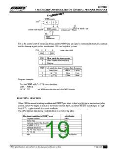
WDT counter
fc/217
0
1
2
3
F/F
R
S
RESET pin
Q
WDT control
counter clear request
system reset
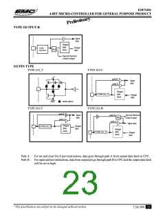
P21
WDT
command port
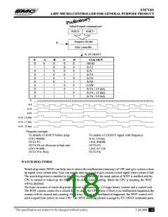
P21 is the control port of watch-dog-timer, and the WDT time up signal is connected to reset pin, user can
use this time up signal (active low) to reset CPU and initialize system.
P21
3
2
1
0
initial value :0000
CWC
*
*
WDT
CWC
Clear watch-dog-timer counter
Clear counter then return to 1
Nothing
0
1
WDT Set watch-dog-timer
detect time
System clock frequency
4MHz
32KHz
3 x 217 /fc
7 x 217 /fc
98ms
229ms
12sec
28sec
0
1
Program example:
To clear WDT with 7 x 217/fc detection time.
LDIA #0001B;
OUTA P21
:
; set WDT detection time and clear WDT counter
:
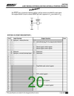
RESETTING FUNCTION
When CPU in normal working condition and RESET pin holds in low level for three instruction cycles
at least, then CPU begins to initialize the whole internal states, and when RESET pin changes to high
level, CPU begins to work in normal condition.
The CPU internal state during reset condition is as following table :
Hardware condition in RESET state
Program counter
Status flag
Initial value
000h
01h
Interrupt enable flip-flop ( EI )
MASK0 ,1, 2, 3
00h
00h
Interrupt latch(IL)
P4, P5, P16, P25, P28
P1, P7, P8
00h
00h
0Fh
Start oscillation
XIN
* This specification are subject to be changed without notice.
19
7.20.1999

 ELAN [ ELAN MICROELECTRONICS CORP ]