EM73201
4-BIT MICRO-CONTROLLER FOR GENERAL PURPOSE PRODUCT
During sleep and hold condition, CPU holds the system's internal status with a low power consumption, for
the sleep mode, the system clock will be stoped in the sleep condition and system need a warm up time for
the stability of system clock running after wakeup . In the other way, for the hold mode, the system clock
does not stop at all and it does not need a warm-up time any way.
The sleep and hold mode is controlled by Port 16 and released by P0(0..3)/WAKEUP0-3.
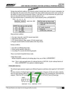
P16
3
2
1
0
initial value :0000
WM SE SWWT
WM Set wake-up release mode
0
Wake-up in edge release mode
1
Reserved
SWWT Set wake-up warm-up time
0 0 218 /XIN
0 1 214 /XIN
1 0 216 /XIN
1 1 Hold mode
SE Enable sleep/hold
0
1
Reserved
Enable sleep / hold rnode
Sleep and hold condition:
1. Osc stop ( sleep only ) and CPU internal status held .
2. Internal time base clear to"0"
3. CPU internal memory ,flags, register, I/O held original states.
4. Program counter hold the executed address after sleep release.
Release condition:
1. Osc start to oscillating.(sleep only)
2. Warm-up time passing ( sleep only ).
3. According PC to execute the following program.
There is one kind of sleep/hold release mode .
1.Edge release mode:
Release sleep/hold condition by the falling edge of any one of P0(0..3)/WAKEUP0-3.
Note : There is only one mask option for weakeup function in EM73201. So,the weakeup function of
P0(0..3)/WAKEUP0..3 are enabled or disabled together.
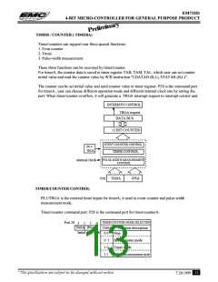
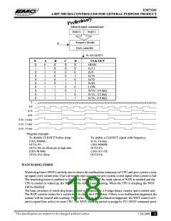
INFRARED SIGNAL
The infrared signal generator supports user different frequencies and duties clock signal by P1.0/CLKOUT
pin.
The basic structure of infrared signal generator is composed by a frequency divider and a duty controller,
these two parts generate differen frequencies and dutyies according to the command port, Port4 and Port5,
assigned . When the CPU is reseted, the CPU is reseted, the P1.0/CLKOUT pin will keep high.
PORT5
E
PORT4
A
3
B
2
C
D
3
2
1
0
1
0
initial state : 0 x x x initial state : 0 0 0 0
* This specification are subject to be changed without notice.
17
7.20.1999

 ELAN [ ELAN MICROELECTRONICS CORP ]