EM73201
4-BIT MICRO-CONTROLLER FOR GENERAL PURPOSE PRODUCT
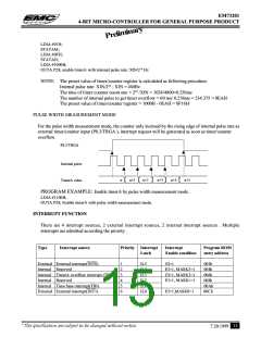
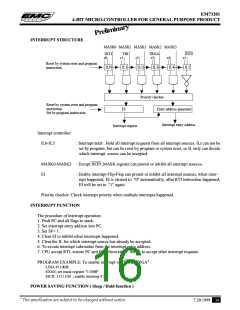
INTERRUPT STRUCTURE
MASK0 MASK1 MASK1 MASK2 MASK3
INT1
r0
TBI
r1
TRGA
r3
INT0
r5
r2
IL2
r4
IL4
Reset by system reset and program
instruction
IL0
IL1
IL3
IL5
Priority checker
Reset by system reset and program
instruction
Set by program instruction
EI
Entry address generator
Interrupt entry address
Interrupt request
Interrupt controller:
IL0-IL5
: Interrupt latch . Hold all interrupt requests from all interrupt sources. ILr can not be
set by program, but can be reset by program or system reset, so IL only can decide
which interrupt source can be accepted.
MASK0-MASK3 : Except INT0 ,MASK register can promit or inhibit all interrupt sources.
EI
: Enable interrupt Flip-Flop can promit or inhibit all interrupt sources, when inter-
rupt happened, EI is cleared to "0" automatically, after RTI instruction happened,
EI will be set to "1" again .
Priority checker: Check interrupt priority when multiple interrupts happened.
INTERRUPT FUNCTION
The procedure of interrupt operation:
1. Push PC and all flags to stack.
2. Set interrupt entry address into PC.
3. Set SF= 1.
4. Clear EI to inhibit other interrupts happened.
5. Clear the IL for which interrupt source has already be accepted.
6. To excute interrupt subroutine from the interrupt entry address.
7. CPU accept RTI, restore PC and flags from stack . Set EI to accept other interrupt requests.
PROGRAM EXAMPLE: To enable interrupt of "INT0, TRGA"
LDIA #1100B;
EXAE; set mask register "1100B"
EICIL 111111B ; enable interrupt F.F.
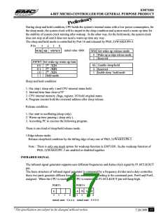
POWER SAVING FUNCTION ( Sleep / Hold functlon )
* This specification are subject to be changed without notice.
7.20.1999 16

 ELAN [ ELAN MICROELECTRONICS CORP ]