VS1005g Datasheet
10 VS1005 PERIPHERALS AND REGISTERS
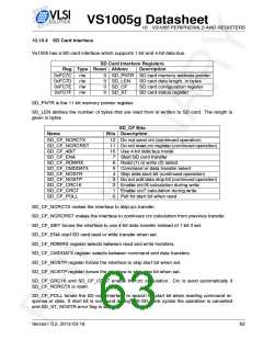
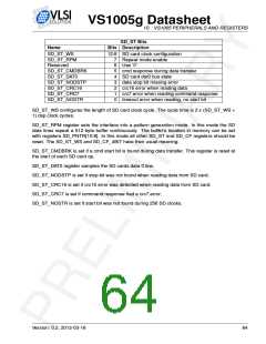
SD_ST Bits
Name
Bits Description
SD_ST_WS
12:8 SD card clock configuration
SD_ST_RPM
Reserved
7
6
5
4
3
2
1
0
Repeat mode enable
Use ’0’
SD_ST_CMDBRK
SD_ST_DAT0
SD_ST_NODSTP
SD_ST_CRC16
SD_ST_CRC7
SD_ST_NOSTR
cmd response during data transfer
SD card dat0 bus state
data stop bit missing error
crc16 error when reading data
crc7 error when reading command response
timeout error when reading, no start bit
SD_ST_WS configures the length of SD card clock cycle. The cycle time is 2 x (SD_ST_WS +
1) dsp clock cycles.
SD_ST_RPM register sets the interface into a pattern generation mode. In this mode the SD
data lines repeat a 512 byte buffer continuously. The buffer’s location in memory can be set
with registers SD_PNTR[10:8]. In this mode all other SD_ST and SD_CF registers should be
reset. The SD_ST_WS and SD_CF_4BIT have their usual meaning.
SD_ST_CMDBRK is set if a cmd start bit is found during data transfer. This register is reset at
the start of each SD card op.
SD_ST_DAT0 register samples the SD cards data 0 line.
SD_ST_NODSTP is set if stop bit was not found when reading data from SD card.
SD_ST_CRC16 is set if crc16 error was detected when reading data from SD card.
SD_ST_CRC7 is set if command response had a crc7 error.
SD_ST_NOSTR is set if start bit was not found during 256 SD clocks.
Version: 0.2, 2012-03-16
64

 ETC [ ETC ]