LM2596
3.0A, 15V, Step-Down Switching Regulator
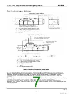
Test Circuit and Layout Guidelines
Figure 2. Typical Test Circuits and Layout Guide
As in any switching regulator, layout is very important. Rapidly switching currents associated with wiring inductance can
generate voltage transients which can cause problems. For minimal inductance and ground loops, the wires indicated by
heavy lines should be wide printed circuit traces and should be kept as short as possible. For best results, external
components should be located as close to the switcher lC as possible using ground plane construction or single point
grounding.
If open core inductors are used, special care must be taken as to the location and positioning of this type of inductor. Allowing
the inductor flux to intersect sensitive feedback, lC groundpath and COUT wiring can cause problems.
When using the adjustable version, special care must be taken as to the location of the feedback resistors and the
associated wiring. Physically locate both resistors near the IC, and route the wiring away from the inductor, especially an open
core type of inductor.
HTC
7
Oct 2004 - Rev 0

 ETC [ ETC ]