LM2596
3.0A, 15V, Step-Down Switching Regulator
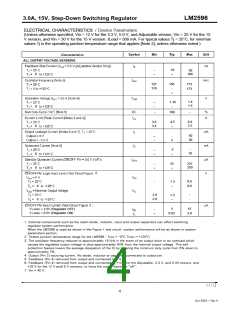
ELECTRICAL CHARACTERISTICS / Device Parameters
(Unless otherwise specified, Vin = 12 V for the 3.3 V, 5.0 V, and Adjustable version, Vin = 25 V for the 12
V version, and Vin = 30 V for the 15 V version. ILoad = 500 mA. For typical values Tj = 25°C, for min/max
values Tj is the operating junction temperature range that applies [Note 2], unless otherwise noted.)
10
50
0
100
127
110
150
173
173
1.4
1.5
1.16
0
0
100
4.5
-
3.6
3.4
6.9
7.5
50
30
-
2
-
5
10
0
0
250
2
-
0.6
0.6
1.3
1.3
0
0
-
-
2.0
2.0
2
5
15
V LOGIC = 2.5V (Regulator OFF)
V LOGIC = 0.5V (Regulator ON)
0.02
5.0
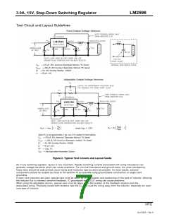
1. External components such as the catch diode, inductor, input and output capacitors can affect switching
regulator system performance.
When the LM2596 is used as shown in the Figure 1 test circuit, system performance will be as shown in system
parameters section .
2. Tested junction temperature range for the LM2596 : TLOW = –0°C THIGH = +125°C
3. The oscillator frequency reduces to approximately 18 kHz in the event of an output short or an overload which
causes the regulated output voltage to drop approximately 40% from the nominal output voltage. This self
protection feature lowers the average dissipation of the IC by lowering the minimum duty cycle from 5% down to
approximately 2%.
4. Output (Pin 2) sourcing current. No diode, inductor or capacitor connected to output pin.
5. Feedback (Pin 4) removed from output and connected to 0 V.
6. Feedback (Pin 4) removed from output and connected to +12 V for the Adjustable, 3.3 V, and 5.0V ersions, and
+25 V for the 12 V and15 V versions, to force the output transistor “off”.
7. Vin = 40 V.
HTC
4
Oct 2004 - Rev 0

 ETC [ ETC ]