Philips Semiconductors
Product specification
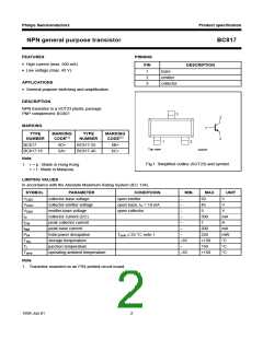
NPN general purpose transistor
BC817
THERMAL CHARACTERISTICS
SYMBOL
PARAMETER
CONDITIONS
note 1
VALUE
UNIT
Rth j-a
thermal resistance from junction to ambient
500
K/W
Note
1. Transistor mounted on an FR4 printed-circuit board.
CHARACTERISTICS
Tj = 25 °C unless otherwise specified.
SYMBOL
PARAMETER
CONDITIONS
IE = 0; VCB = 20 V
MIN. TYP. MAX. UNIT
ICBO
collector cut-off current
−
−
−
−
−
−
100
5
nA
µA
nA
IE = 0; VCB = 20 V; Tj = 150 °C
IEBO
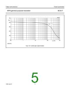
hFE
emitter cut-off current
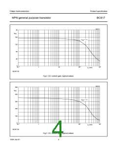
DC current gain
BC817
IC = 0; VEB = 5 V
100
IC = 100 mA; VCE = 1 V; note 1;
see Figs 2, 3 and 4
100
100
160
250
40
−
−
−
−
−
−
−
5
−
600
250
400
600
−
BC817-16
BC817-25
BC817-40
hFE
VCEsat
VBE
Cc
DC current gain
IC = 500 mA; VCE = 1 V; note 1
collector-emitter saturation voltage IC = 500 mA; IB = 50 mA; note 1
−
700
1.2
−
mV
V
base-emitter voltage
collector capacitance
transition frequency
IC = 500 mA; VCE = 1 V; note 2
IE = ie = 0; VCB = 10 V; f = 1 MHz;
IC = 10 mA; VCE = 5 V; f = 100 MHz;
−
−
pF
fT
100
−
MHz
Notes
1. Pulse test: tp ≤ 300 µs; δ ≤ 0.02.
2. VBE decreases by approx. 2 mV/K with increasing temperature.
1999 Jun 01
3

 ETC [ ETC ]