Electrical specifications
TDA7851L
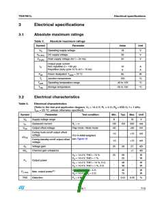
Table 4.
Electrical characteristics (continued)
(Refer to the test and application diagram, VS = 14.4 V; RL = 4 Ω; Rg = 600 Ω; f = 1 kHz;
amb = 25 °C; unless otherwise specified).
Parameter Test condition
T
Symbol
Min.
Typ.
Max.
Unit
"A" Weighted
35
50
-
µV
µV
eNo
Output noise
-
Bw = 20 Hz to 20 kHz
f = 100 Hz; Vr = 1 Vrms
PO = 0.5 W
100
SVR
fch
Supply voltage rejection
High cut-off frequency
Input impedance
50
100
70
70
-
-
dB
KHz
KΩ
300
100
Ri
130
f = 1 kHz PO = 4 W
f = 10 kHz PO = 4 W
60
-
70
60
-
-
dB
dB
CT
Cross talk
VSt-by = 1.2 V
VSt-by = 0
-
-
-
-
20
10
1
µA
µA
µA
V
ISB
Standby current consumption
Standby pin current
Ipin5
VSt-by = 1.2 V to 2.6 V
(Amp: ON)
-
-
VSB out Standby out threshold voltage
2.6
-
-
-
VSB in
AM
Standby in threshold voltage
Mute attenuation
(Amp: OFF)
POref = 4 W
-
1.2
-
V
80
2.6
-
90
-
dB
V
VM out
VM in
Mute out threshold voltage
Mute in threshold voltage
(Amp: Play)
(Amp: Mute)
-
-
1.2
V
(Amp: Mute)
Att ≥ 80 dB; POref = 4 W
6.7
7
-
V
VAM in
VS automute threshold
Muting pin current
(Amp: Play)
Att < 0.1 dB; PO = 0.5 W
-
7.5
12
-
8
V
VMUTE = 1.2 V
7
18
18
µA
µA
(Sourced current)
Ipin23
VMUTE = 2.6 V
-5
Clipping detector
CDLK
Clip detector high leakage current Cd off
-
-
-
0
0.2
2
1
0.4
-
µA
V
CDSAT Clip detector saturation voltage
CDTHD Clip detector THD level
1. Saturated square wave output
DC On; ICD = 1 mA
-
%
8/15
Rev 1

 ETC [ ETC ]