EAGLE
PRELIMINARY
Ver 1.3
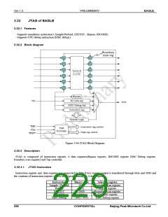
3.32.3.2 Tap Controller
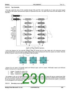
User may control the state of TAP controller through TMS and TCK. TAP controller has 16 states and control signals
governed by data register and instruction register are generated each state. The figure below shows the state diagram of Tap
controller.
Figure 3-65 Tap Controller Operation
In this state diagram, the Tap controller operation states are divided into two sides. Right side is for Instruction register
control and left side is for data register control. However, the control mechanism for these two registers are similar. Basically
the flow of register control is in the order of capture, shift and update.
Register has two inputs: PI (Parallel input) and SI(Serial input), and two outputs: PO(Parallel output) and SO(Serial
Output). Each process is responsible for:
1. Capture : Transfer PI’s value to SO
2. Shift : Transfer SI’s value to SO
3. Update : Transfer SO’s value to PO
For example, in the case of control instruction register, Select IR-SCAN state and Capture-IR state are entered using TMS
and TCK. In Capture-IR state, the current instruction is copied into SO and a new instruction is shifted in from TDI in Shift-
IR. In Exit1-IR state, instruction shifting is completed. In Update-IR state, the SO value in Instruction register is transferred
to PO and applied to new instruction.
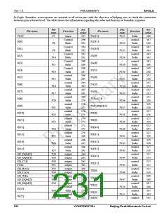
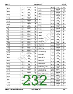
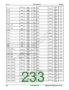
3.32.3.3 Boundary scan register
Beijing Peak Microtech Co.Ltd.
CONFIDENTIAL
230

 ETC [ ETC ]