Power Driver Integrated Full Digital Audio Amplifier
NTP-8230
11. OUTPUT INTERFACE
11.1. Output Configuration
The output mode of NTP-8230 is 2.0 stereo reproduction mode and 2.1 reproduction mode. To
produce proper output signal, register 0x35~0x37 should be set to appropriate values.
11.2. AM Interference Relief Mode
The NTP-8230 has AM interference reduction mode. In this mode SNR performance of NTP-8230 can
be degrade down to 90 dB and the PWM switching frequency is spread from 384kHz through 768kHz.
11.3. PWM Output Mapper
Any internal channel that produces a PWM output can be assigned to any PWM output hardware port
(or pin) by mapping output port register. This feature is very helpful for the hardware designer because
it can relieve difficulties in the power stage signal routing and channel assignment if the output channel
order is fixed. See the system register address 0x35~0x37 in the Appendix A.
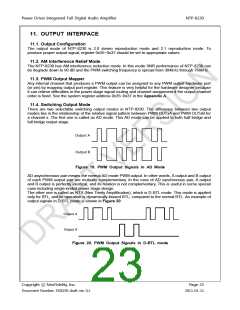
11.4. Switching Output Mode
There are two selectable switching output modes in NTP-8230. The difference between two output
modes lies in the relationship of the relative signal pattern between PWM OUTxA and PWM OUTxB for
a channel x. The first one is called as AD mode. This AD mode can be applied to both half bridge and
full bridge output stage.
Output A
Output B
Figure 19. PWM Output Signals in AD Mode
AD asynchronous pair means the normal AD mode PWM output. In other words, A output and B output
of each PWM output pair are mutually complementary. In the case of AD synchronous pair, A output
and B output is perfectly identical, and its relation is not complementary. This is useful in some special
case including single-ended power stage design.
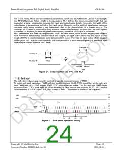
The other one is called as NTX (Neo Trinity Amplification), which is D-BTL mode. This mode is applied
only for BTL, and its operation is dynamically-biased BTL, compared to the normal BTL. An example of
output signals in D-BTL mode is shown in Figure 20
Output A
Output B
Figure 20. PWM Output Signals in D-BTL mode
Copyright ⓒ NeoFidelity, Inc.
Page 23
Document Number: DS8230 draft ver. 0.1
2011-01-11

 ETC [ ETC ]