29
Voltage Sensing
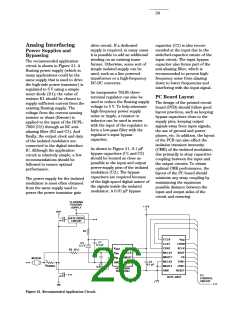
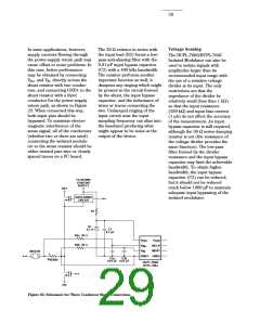
In some applications, however,
supply currents flowing through
the power-supply return path may
cause offset or noise problems. In
this case, better performance
may be obtained by connecting
The 39 Ω resistor in series with
the input lead (R2) forms a low-
pass anti-aliasing filter with the
0.01 µF input bypass capacitor
(C2) with a 400 kHz bandwidth.
The resistor performs another
important function as well; it
dampens any ringing which might
be present in the circuit formed
by the shunt, the input bypass
capacitor, and the inductance of
wires or traces connecting the
two. Undamped ringing of the
input circuit near the input
The HCPL-7860/HCPL-786J
Isolated Modulator can also be
used to isolate signals with
amplitudes larger than its
recommended input range with
the use of a resistive voltage
divider at its input. The only
restrictions are that the
VIN+ and VIN- directly across the
shunt resistor with two conduc-
tors, and connecting GND1 to the
shunt resistor with a third
conductor for the power-supply
return path, as shown in Figure
23. When connected this way,
both input pins should be
bypassed. To minimize electro-
magnetic interference of the
sense signal, all of the conductors
(whether two or three are used)
connecting the isolated modula-
tor to the sense resistor should be
either twisted pair wire or closely
spaced traces on a PC board.
impedance of the divider be
relatively small (less than 1 kΩ)
so that the input resistance
(280 kΩ) and input bias current
(1 µA) do not affect the accuracy
of the measurement. An input
bypass capacitor is still required,
although the 39 Ω series damping
resistor is not (the resistance of
the voltage divider provides the
same function). The low-pass
filter formed by the divider
resistance and the input bypass
capacitor may limit the achievable
bandwidth. To obtain higher
bandwidth, the input bypass
capacitor (C2) can be reduced,
but it should not be reduced
much below 1000 pF to maintain
adequate input bypassing of the
isolated modulator.
sampling frequency can alias into
the baseband producing what
might appear to be noise at the
output of the device.
FLOATING
POSITIVE
SUPPLY
HV+
GATE DRIVE
CIRCUIT
R1
D1
5.1 V
C1
0.1 µF
R2a 39 Ω
V
V
V
V
DD2
DD1
IN+
IN-
R2b 39 Ω
MCLK
MDAT
MOTOR
+
-
GND1 GND2
C2a
C2b
R
SENSE
0.01 µF 0.01 µF
HCPL-7860/
HCPL-786J
HV-
Figure 23. Schematic for Three Conductor Shunt Connection.

 ETC [ ETC ]