28
drops across the leads carrying
the load current should have no
impact on the measured voltage.
a tightly twisted pair of wires can
accomplish the same thing.
This allows a single pair of wires
or PC board traces to connect the
isolated modulator circuit to the
shunt resistor. By referencing the
input circuit to the negative side
of the sense resistor, any load
current induced noise transients
on the shunt are seen as a
Also, multiple layers of the PC
board can be used to increase
current carrying capacity.
Numerous plated-through vias
should surround each non-Kelvin
terminal of the shunt to help
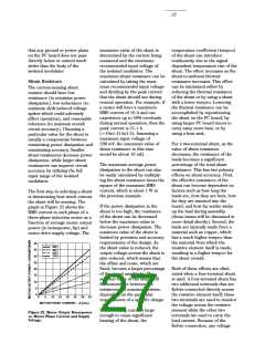
Several four-terminal shunts from
Isotek (Isabellenhütte) suitable
for sensing currents in motor
drives up to 71 Arms (71 hp or
53 kW) are shown in Table 9; the
maximum current and motor
power range for each of the PBV-
series shunts are indicated. For
shunt resistances from 50 mΩ
down to 10 mΩ, the maximum
current is limited by the input
voltage range of the isolated
modulator. For the 5 mΩ and
2 mΩ shunts, a heat sink may be
required due to the increased
power dissipation at higher
currents.
common-mode signal and will not
distribute the current between the interfere with the current-sense
layers of the PC board. The PC
board should use 2 or 4 oz.
copper for the layers, resulting in
a current carrying capacity in
excess of 20 A. Making the
current carrying traces on the PC
board fairly large can also
improve the shunt’s power
dissipation capability by acting as
a heat sink. Liberal use of vias
where the load current enters and
exits the PC board is also
signal. This is important because
the large load currents flowing
through the motor drive, along
with the parasitic inductances
inherent in the wiring of the
circuit, can generate both noise
spikes and offsets that are
relatively large compared to the
small voltages that are being
measured across the current
shunt.
When laying out a PC board for
the shunts, a couple of points
should be kept in mind. The
recommended.
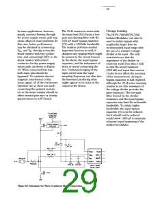
If the same power supply is used
both for the gate drive circuit and
for the current sensing circuit, it
is very important that the connec-
tion from GND1 of the isolated
modulator to the sense resistor
be the only return path for
Shunt Connections
Kelvin connections to the shunt
should be brought together under
the body of the shunt and then
run very close to each other to
the input of the isolated modula-
tor; this minimizes the loop area
of the connection and reduces the
possibility of stray magnetic
fields from interfering with the
measured signal. If the shunt is
not located on the same PC board
as the isolated modulator circuit,
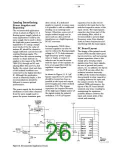
The recommended method for
connecting the isolated modula-
tor to the shunt resistor is shown
in Figure 21. VIN+ (pin 2 of the
HPCL-7860/HCPL-786J) is
connected to the positive
terminal of the shunt resistor,
while VIN- (pin 3) is shorted to
GND1 with the power-supply
return path functioning as the
sense line to the negative
supply current to the gate drive
power supply in order to
eliminate potential ground loop
problems. The only direct con-
nection between the isolated
modulator circuit and the gate
drive circuit should be the
positive power supply line.
terminal of the current shunt.
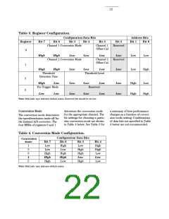
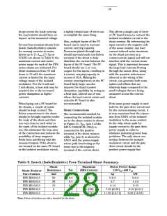
Table 9. Isotek (Isabellenhütte) Four-Terminal Shunt Summary.
Shunt
Resistance
Maximum
RMS Current
Motor Power Range
120 V -440 V
Tol.
%
ac
ac
Shunt Resistor
Part Number
mΩ
50
20
10
5
A
3
7
hp
kW
PBV-R050-0.5
PBV-R020-0.5
PBV-R010-0.5
PBV-R005-0.5
PBV-R002-0.5
0.5
0.5
0.5
0.5
0.5
0.8-3
2-7
0.6-2
1.4-5
14
25 [28]
39 [71]
4-14
3-10
7-25 [8-28]
11-39 [19-71]
5-19 [6-21]
8-29 [14-53]
2
Note: Values in brackets are with a heatsink for the shunt.

 ETC [ ETC ]