GD150HFL120C2S
IGBT Module
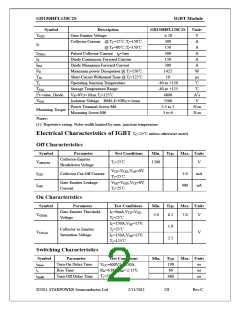
tf
Fall Time
55
ns
VCC=600V,IC=150A,
RG=6.8Ω,VGE=±15V,
Tj=25℃
Turn-On Switching
Loss
Eon
11.2
9.8
mJ
mJ
Turn-Off Switching
Loss
Eoff
td(on)
tr
td(off)
tf
Turn-On Delay Time
Rise Time
220
60
ns
ns
ns
ns
Turn-Off Delay Time
Fall Time
530
75
VCC=600V,IC=150A,
RG=6.8Ω,VGE=±15V,
Tj=125℃
Turn-On Switching
Loss
Eon
Eoff
16.7
15.3
mJ
mJ
Turn-Off Switching
Loss
Cies
Input Capacitance
Output Capacitance
Reverse Transfer
Capacitance
10.6
0.71
nF
nF
VCE=25V,f=1MHz,
VGE=0V
Coes
Cres
0.47
nF
t ≤10μs,V =15V,
C
S
GE
ISC
SC Data
Tj=125℃,VCC=900V,
VCEM≤1200V
650
A
LCE
Stray inductance
Module lead
20
nH
RCC’+EE’
resistance, terminal to TC=25℃
0.35
mΩ
chip
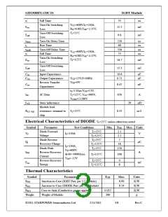
Electrical Characteristics of DIODE TC=25℃unless otherwise noted
Symbol
Parameter
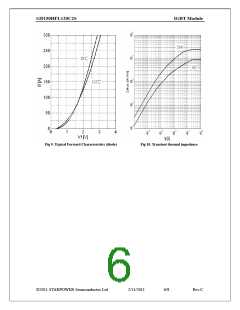
Diode Forward
Voltage
Test Conditions
Tj=25℃
Min. Typ. Max. Units
2.1
VF
IF=150A
V
μC
Tj=125℃
Tj=25℃
Tj=125℃
Tj=25℃
2.2
Diode Reverse
Recovery Charge
Diode Peak
7
Qr
18
IF=150A,
150
VR=600V,
IRM
A
Reverse Recovery
Current
di/dt=-4800A/μs,
VGE=-15V
Tj=125℃
190
Reverse Recovery
Energy
Tj=25℃
4
Erec
mJ
Tj=125℃
8
Thermal Characteristics
Symbol
RθJC
Parameter
Junction-to-Case (IGBT Part, per 1/2 Module)
Typ.
Max.
0.09
0.24
Units
K/W
K/W
K/W
g
RθJC
Junction-to-Case (DIODE Part, per 1/2 Module)
Case-to-Sink (Conductive grease applied)
Weight of Module
RθCS
0.035
300
Weight
©2011 STARPOWER Semiconductor Ltd.
2/11/2011
3/8
Rev.C

 ETC [ ETC ]