Sonar Ranging Module
SRM400
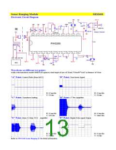
Electronic Circuit Diagram
Vref
Vcc
Test "C"
BAV99
1.5K
3
4
100
220u
1
2
Vref
Vcc
Vreg
2200p
20K
1K
IFT
400EP14D
Vref
User
Side
47K
22p 3.3K
100u
100u
100u
511
BSS123
Vcc
Vcc
Ultrasonic Transducer
660KHZ
15
20
19
18
17
16
14
13
12
11
3
2
1
3
2
1
3
2
1
Test "B"
6.8K
PW0268
MMBT3904
10K
1
2
3
4
5
6
7
8
9
10
2200p
4.7K
4.7K
2.7K
10n
BAV99
Echo High Level Pulse
10n
33K
Test "F"
680p 680p
13K
Test "A"
Test "D"
MCU
Test "E"
470p
Vref
Vref
Vref
Waveforms at different test points:
works with transducer model 400EP14D against a hard target of size of 20cmL*20cmW*1cmT at distance of 50cm
“A” Point: Control Pulse (from MCU) “B” Point: Tone bursts Signal
H: 0.5ms/div
V: 5V/div
H: 0.5ms/div
V: 5V/div
“C” Point: Transducer loading
“D” Point: 1st Pre-Amplifier
H: 0.5ms/div
V: 50V/div
H: 0.5ms/div
V: 20mV/div
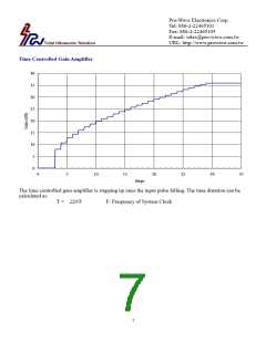
“E” Point: Main 32 Steps TCG Amplifier
“F” Point: Digital Echo signal Output
H: 0.5ms/div
V: 1V/div
H: 0.5ms/div
V: 5V/div
Refer to PW-0268 Sonar Ranging IC for detail information.

 ETC [ ETC ]