Application Notes
PT4120/4140 Series
Adjusting the Output Voltage of the PT4120/
PT4140 Series of Isolated DC/DC Converters
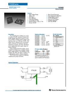
The factory pre-set output voltage of Power Trends’
PT4120 and PT4140 series of isolated DC/DC converters
may be adjusted within 10% of nominal. Adjustment is
4. Never connect capacitors to Vo adjust. Any capacitance
added to the Vo adjust control pin will affect the stability of
the ISR.
1
made from the secondary side of the regulator with a
The values of (R1) [adjust down], and R2 [adjust up], can also
be calculated using the following formulas.
single external resistor. For the input voltage range
specified in the data sheet Table 1 gives the allowable
adjustment range for each model, as Vo (min) and Vo (max).
Ko (Va – Vr)
Vr (Vo – Va)
(R1)
R2
=
=
– Rs
kΩ
kΩ
Adjust Up: An increase in the output voltage is obtained
by adding a resistor, R2 between pin 6 (Vo adjust), and pin
4 (-Vout).
Ko
(Va – Vo)
– Rs
Adjust Down: Add a resistor (R1), between pin 6 (Vo ad-
just) and pin 5 (+Vout).
Where Vo = Original output voltage
Va = Adjusted output voltage
Vr = Reference voltage (Table 1)
Ko = Multiplier constant (Table 1)
Rs = Internal series resistance (Table 1)
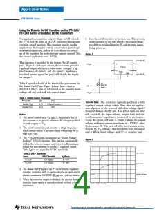
Refer to Figure 1 and Table 2 for both the placement
and value of the required resistor, (R1) or R2.
Notes:
1. The PT4120 and PT4140 series of DC/DC converters
incorporate isolation between the Vin and Vo terminals.
Adjustment of the output voltage is made to the
regulation circuit on the secondary or output side of
the converter.
Figure 1
+Vo
2. The maximum rated output power for this series is
20W. An increase in the output voltage may therefore
require a corresponding reduction in the maximum
output current (see Table 1). The revised maximum
output current must be determined as follows:-
+Vin
(R1)
Adj Down
3
2
5
4
+Vin
+Vout
PT4120/40
–Vin
–Vout
Remote
R2
Adj
Up
On/Off
Vo(adj)
6
20
1
Io(max)
=
A,
or 5A, whichever is less.
–Vin
Va
–Vo
Where Va is the adjusted ouput voltage.
3. Use only a single 1% resistor in either the (R1) or R2
location. Place the resistor as close to the ISR as possible.
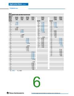
Table 1
DC/DC CONVERTER ADJUSTMENT RANGE AND FORMULA PARAMETERS
Series Pt #
48V Bus
24V Bus
Max Current 2
Vo(nom)
Va(min)
Va(max)
Vr
PT4126
PT4146
5A
PT4129
PT4127
PT4147
5A
PT4128
PT4148
5A
PT4121
PT4141
5A
PT4122
PT4142
4A
PT4125
PT4123
PT4143
1.6A
12.0
10.8
13.2
2.5
139.8
110.0
PT4124
PT4144
1.3A
15.0
13.5
16.5
2.5
137.6
90.9
5A
3.8A
5.2V
4.75
5.75
2.5
1.5
1.35
1.65
1.225
67.07
43.2
1.65
1.49
1.81
1.225
63.9
66.5
1.8
1.62
1.98
1.225
69.7
2.5
2.25
2.75
1.225
64.2
3.3
5.0
4.5
5.5
2.5
125.2
187.0
2.95
3.65
1.225
69.3
187.0
Ko (V·kΩ)
Rs (kΩ)
134.7
243.0
110.0
187.0
For technical support and more information, see inside back cover or visit www.ti.com

 ETC [ ETC ]