Application Notes
PT4120/4140 Series
Using the Remote On/Off Function on the PT4120/
PT4140 Series of Isolated DC/DC Converters
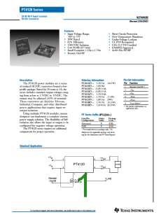
For applications requiring output voltage on/off control,
the PT4120/4140 series of DC/DC converters incorporate
a remote on/off function. This function may be used in
applications that require battery conservation, power-up/
shutdown sequencing, and/or to co-ordinate the power-
up of the regulator for active in-rush current control. (See
the related application note, AN21).
6. Keep the on/off transition to less than 1ms. This prevents
erratic operation of the ISR, whereby the output voltage
may drift un-regulated between 0V and the rated output
during power-up.
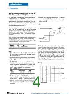
Figure 1
+V o
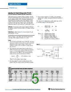
This function is provided by the Remote On/Off control,
pin1. If pin 1 is left open-circuit, the converter provides a
regulated output whenever a valid source voltage3 is ap-
plied between +Vin(pin 3), and –Vin (pin 2). Applying a
low-level ground signal 1 to pin 1 will disable the regula-
tor output 5.
3
2
5
4
+Vin
+Vout
+V in
PT4121
–Vin
–Vout
Remote
On/Off
Vo(adj)
6
–V o
1
Q1
BSS138
Table 1 provides details of the threshold requirements for
the Remote On/Off pin. Figure 1 shows how a discrete
MOSFET (Q1) 4, may be referenced to the negative input
voltage rail and used with this control input.
Inh
Note
2
–V in
Table 1 Inhibit Control Thresholds
Parameter
min
max
Turn-On Time: The converter typically produces a fully
regulated output voltage within 50ms after the applica-
tion of power, or the removal of the low voltage signal 6
from the Remote On/Off pin. The actual turn-on time
will vary with the input voltage, output load, and the
total amount of capacitance connected to the output.
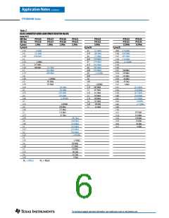
Using the circuit of Figure 1, Figure 2 shows the output
voltage and input current waveforms of a PT4121 after
Q1 is turned off. The turn off of Q1 corresponds to the
drop in Q1 Vgs voltage. The waveforms were measured
with a 48Vdc input voltage, and 2.75-A resistive load.
2, 4
Enable (VIH
Disable (VIL
)
)
2.5V
–0.3V
(Open Circuit)
0.8V
Notes:
1. The on/off control uses -Vin (pin 2), the primary side of
the converter as its ground reference. All voltages specified
are with respect to -Vin.
2. The on/off control internal circuitry is a high impedance
10µA current source. The open-circuit voltage may be as
high as 8.3Vdc.
3. The PT4120/40 series incorporates an “Under Voltage
Lockout” (UVLO) function. This function automatically
inhibits the converter output until there is sufficient input
voltage for the converter to produce a regulated output.
Table 2 gives the applicable UVLO thresholds.
Figure 2
Vout (2V/Div)
Iin (0.2A/Div)
Table 2 UVLO Thresholds
Series
UVLO Threshold
Vin Range
PT4120
PT4140
31V Typical
15V Typical
36 – 75V
18 – 40V
4. The Remote On/Off input of the PT4120/40 series regulators
must be controlled with an open-collector (or open-drain)
discrete transistor or MOSFET. Do not use a pull-up resistor.
Q1 Vgs (10V/Div)
5. When the converter output is disabled, the current drawn
from the input supply is typically reduced to 8mA (16mA
maximum).
HORIZ. SCALE: 5ms/Div
For technical support and more information, see inside back cover or visit www.ti.com

 ETC [ ETC ]