AP902M
FREQUENCY AND CLOCK DISPLAY CONTROLLER
COB
PIN NO
23
PIN NAME
I/O
FUNCTION
MIN_SET
HR_SET
NC
ISU
ISU
-
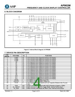
Minute Setting for Time and Alarm (Together with AL_DISP). Internal Pull Up.
Hour Setting for Time and Alarm (Together with AL_DISP). Internal Pull Up.
No Connection
24
25
26
CLKFREQ_SEL ISD
Clock or Frequency Display Mode. Internal Pull-Down Input. When the Input
is in Low Status, Clock will be Displayed. When the Input is in High Status,
Radio Frequency will be Displayed.
27
28
29
30
31
32
33
34
35
36
AL_SIG
AL_OUT
NC
OD
O
-
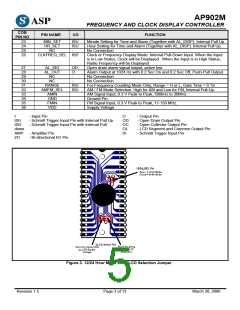
Open drain alarm signal output, active low.
Alarm Output at 1024 Hz with 0.2 Sec On and 0.2 Sec Off, Push-Pull Output.
No Connection
NC
-
No Connection
RANGE
AMFM_SEL
AMIN
ISU
ISU
For Frequency Counting Mode Only, Range = H or L, Gate Time = 0.1S
AM / FM Mode Selection. High for AM and Low for FM, Internal Pull-Up.
AM Signal Input, 0.3 V Peak to Peak, 500kHz to 30MHz.
Ground Pin.
FM Signal Input, 0.3 V Peak to Peak, 11-150 MHz.
Supply Voltage
GND
FMIN
VDD
I
- Input Pin
O
- Output Pin
ISU
ISD
down
- Schmitt Trigger Input Pin with Internal Pull Up
- Schmitt Trigger Input Pin with Internal Pull
OD
OC
OL
IS
- Open Drain Output Pin
- Open Collector Output Pin
- LCD Segment and Common Output Pin
- Schmitt Trigger Input Pin
AMP - Amplifier Pin
I/O - Bi-directional I/O Pin
Figure 3. 12/24 Hour Mode and VLCD Selection Jumper
Revision 1.5
Page 3 of 13
March 30, 2006

 ETC [ ETC ]