Philips Semiconductors
Product specification
2 × 8 W stereo BTL audio output amplifier
with DC volume control
TDA7057AQ
MBG665
MBG666
2.0
30
handbook, halfpage
handbook, halfpage
I
VC
(µA)
V
in
(V)
20
1.6
10
0
1.2
0.8
−10
−20
0.4
0
0
−30
4
8
12
16
20
0
0.4
0.8
1.2
1.6
V
2.0
(V)
V
(V)
P
VC
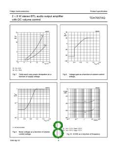
THD = 1 %.
Fig.12 Volume control current as a function of
volume control voltage.
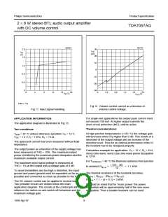
Fig.11 Input signal handling.
For single-end applications the output peak current must
not exceed 100 mA. At higher output currents the
short-circuit protection (MCL) will be active.
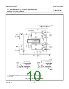
APPLICATION INFORMATION
The application diagram is illustrated in Fig.13.
Thermal considerations:
Test conditions
At high junction temperatures (>125 °C) the voltage gain
will decrease when it is higher than 0 dB. This results in a
decrease of the output voltage and an increase of the
distortion level. Thus for an optimal performance of the IC
the heatsink has to be designed properly.
T
V
amb = 25 °C unless otherwise specified; VP = 12 V;
DC = 1.4 V; fi = 1 kHz; RL = 16 Ω.
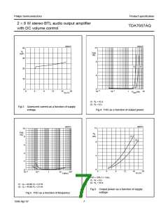
The quiescent current has been measured without load
impedance.
The output power as a function of the supply voltage has
been measured at THD = 10%. The maximum output
power is limited by the maximum power dissipation and the
maximum available output current.
Calculation example for application: VP = 15 V; RL = 8 Ω,
stereo sine wave; worst case sine wave power dissipation
is 12 W.
For Tamb(max) = 40 °C the thermal resistance from junction
(125 – 40)
The maximum input signal voltage is measured at
THD = 1% at the output with a voltage gain of 0 dB.
to ambient Rth j-a
=
= 7.1 K/W
----------------------------
12
To avoid instabilities and too high a distortion, the input
ground and power ground must be separated as far as
possible and connected as close as possible to the IC.
The thermal resistance of the heatsink becomes:
th h-a = Rth j-a − (Rth j-c + Rth c-h);
R
Rth h-a = 7.1 − (4 + 0.1) = 3 K/W.
The DC volume control can be applied in several ways.
Two possible circuits are shown below the main
application diagram. The circuits at the control pin will
influence the switch-on and switch-off behaviour and the
maximum voltage gain.
It should be noted that for ‘music power’ the power
dissipation will be approximately half of the sine wave
dissipation. Thus a smaller heatsink can be used.
1998 Apr 07
9

 ETC [ ETC ]